Home - About AR - Learning Material - Exams - Clubs - Posters
A theoretical, or rather "hypothetical" or "notional" antenna, used as a reference, is the isotropic radiator, which notionally radiates equally in all directions. No real antenna radiates like this, and in fact, theory tells us that an antenna which radiates linear waves in all directions is not possible. The behaviour could be likened to a light-globe, or to the sun.
They are however a favourite device of the marketing department, as if they describe an antenna's gain relative to a isotropic radiator, rather than a dipole, they can increase the number on their glossy brochure by 2.15 dB.
Note that an antenna may be listed as having a "gain" of 0 dBi, but this does not make it an isotropic antenna. A low profile antenna on a locomotive may have a similar figure. A Beverage has a gain of −20 to −10 dBi, but is never-the-less directional, which helps it reject static and interference.
Many antenna designs concentrate the the energy fed into them in a particular direction' while vertical antennas with gain concentrate the signal into a flatter disc. Stacking antennas into arrays can also increase gain. Stacks of halo or other horizontal omni-directional antennas can also flatten the pattern of a horizontal omni signal, and we might use this as a "rover" station in a VHF-UHF contest. This gain is specified in dB, relative to either a dipole or an isotropic radiator.
As we know, a feedline, such as coaxial cable has loss, which can be significant at VHF and UHF, especially if there is some length, such as a feed between a repeater and its antenna(s), even if thicker cable is used. Repeaters typically include duplexers, such as an network of cavity filters; and some include circulators to manage the flow of power, including in the case of an antenna fault. Both of these have some loss, typically listed in dB, and we need to add these together, and to the feedline loss.
One way to consider an antenna systems a to determine the power reaching the feedpoint, being the transmitter power less the losses; then add the gain of the antenna. If 25 watts gets to the antenna, and it has 10 dBd of gain, the effect of the antenna, for stations in the correct location, is that the signal strength is as though a power of 250 watts (10 dB over 25 watts) is fed into a dipole.
I have typically considered the loss and gain, and then applied this to the power of the transmitter.
In any case, the power we calculate is called the ERP, or effective radiated power. In the VHF and UHF broadcasting world (FM radio and TV), licensing is typically for ERP, while for MW and SW (AM), it is for actual power. A variation is the EIRP, a figure 2.15 dB larger than ERP figure.
If we have a simple antenna, such as a dipole or an ordinary vertical (monopole), then as we move away from the resonant frequency the SWR will rise, for example to a point where either the final amplifier is at risk of damage, or protection circuitry winds back the power to protect these stages. With a gain antenna, such as a Yagi, gain may well also drop off outside the design frequency.
Note that if we have a fixed Yagi antenna with a moderate number of elements, it will have moderate gain. It will however have a beamwidth which might take in all the repeaters in a city if we are some distance away, while a longer Yagi, with more elements has more gain, but the beamwidth is narrower, so while the signal to and from the repeater in the centre of the beam will be greater, those a little off-axis may receive less signal. Going from perhaps 4 elements to 8 or 10 might result in the behaviour above.
A rough guide to beamwidth is to look at the angle between the points 3 dB down on the signal at the centre of the main lobe on the azimuth plot (the plan view, meaning the view from above). This is not to say that stations beyond that beam will not receive your signal, but too much further outside it, and the S-points will drop.
Dish antennas will have very narrow beamwidth.
Vertical antennas, especially short ones, less than a quarter-wave; and quarter-wave and five-eighth units require a system of radials for them to provide a reasonable match, and to radiate efficiently. Even if the vendor claims that their antennas (such as half-waves) don't need a ground-plane or radials, they will likely still be improved by a few radials.
There are several options depending on the type of station. For HF verticals mounted on the ground, several radials of reasonably heavy wire, of a quarter-wave, or five-eighth wire for each band of interest are a good option. For DX-peditions, a large number of fine radials is also an option. Note that the idea of these radials is to provide an RF ground-plane, NOT for lightning protection. That said, the radial should be bonded to the grounding system.
When we use an antenna to couple RF energy from a feedline to free space, there is an effective resistance, which can be calculated. This is in addition to ohmic losses, caused by the resistance of the conductor, say if we used thin stainless steel wire for an long low-HF antenna. Given P = I²R, we can determine this via R = P/I², although I suppose that this is taking in the usually small ohmic resistance too. More on Wikipedia: Radiation resistance
There are a range of antenna modelling systems, some for specific formats, and some more general. These can tell the user many things about the proposed antenna, including impedance related parameters, including SWR vs frequency charts; polar plots of the far field elevation and azimuth patterns which can provide information including front-to-back and front-to side ratios; and antenna gain. Some systems can run through a range of optimisations, such as element spacing in a yagi. NEC is a famous example, standing for "Numerical Electromagnetics Code". It was developed by the Lawrence Livermore National Laboratory, a US Government Agency, and thus certain versions are available in the public domain.
NEC uses the method of moments.
The NEC engine is packaged with a graphical user interface, one example being 4nec2, available at: www.qsl.net/4nec2/
It is important to realise that an antenna can give an SWR reading of 2:1, or significantly higher, and still be resonant, if its impedance is other than 50 ohms (assuming that is the impedance of our system). I rather like my delta loop (on 6 metres), but these have an impedance of 102 ohms, or thereabouts. While we could use 50 ohm coax, and a tuner, which some authors do suggest, there are other methods, such as using a quarter-wave section of coax as a matching section. Other antennas may have am impedance of 200, 300, or 450 ohms, or more. In such cases a balun or unun is used to match to coax, such as 50 ohm coax.
These are actual questions from the NCVEC Extra exam pool.
E9A01
What is an isotropic antenna?
A. A grounded antenna used to measure Earth conductivity
B. A horizontally polarized antenna used to compare Yagi antennas
C. A theoretical, omnidirectional antenna used as a reference for antenna gain
D. A spacecraft antenna used to direct signals toward Earth
This is an imaginary antenna, to which a the gain of a real antenna can be referenced, answer C.
E9A02
What is the effective radiated power relative to a dipole of a repeater station with 150 watts transmitter power output, 2 dB feed line loss, 2.2 dB duplexer loss, and 7 dBd antenna gain?
A. 1977 watts
B. 78.7 watts
C. 420 watts
D. 286 watts
Subtracting the total loss of 4.2 dB from the 7 dB gain we get 2.8 dB gain. We know that if we added 3 dB to 150 watts we would get 300 watts. 286 watts is a little less than this, and so answer D is the only viable one.
E9A03
What is the radiation resistance of an antenna?
A. The combined losses of the antenna elements and feed line
B. The specific impedance of the antenna
C. The value of a resistance that would dissipate the same amount of power as that radiated from an antenna
D. The resistance in the atmosphere that an antenna must overcome to be able to radiate a signal
This is the value of a resistance that would dissipate the same amount of power as is radiated by the antenna, answer C.
E9A04
Which of the following factors may affect the feed point impedance of an antenna?
A. Transmission line length
B. Antenna height
C. The settings of an antenna tuner at the transmitter
D. The input power level
This asks about the feedpoint of the antenna, not external factors, and the only one discussing the actual antenna is answer B.
This most strongly affects horizontal HF wire antennas above a conductive ground or other surface. Also, a 40 metre dipole antenna which works and matches well over dry sandy soil at low height in an empty beach-side parking area may present a very poor match in a Darwin backyard, in proximity to a metal fence.
E9A05
What is included in the total resistance of an antenna system?
A. Radiation resistance plus space impedance
B. Radiation resistance plus transmission resistance
C. Transmission-line resistance plus radiation resistance
D. Radiation resistance plus ohmic resistance
This is simply radiation resistance, plus ohmic resistance, answer D.
E9A06
What is the effective radiated power relative to a dipole of a repeater station with 200 watts transmitter power output, 4 dB feed line loss, 3.2 dB duplexer loss, 0.8 dB circulator loss, and 10 dBd antenna gain?
A. 317 watts
B. 2000 watts
C. 126 watts
D. 300 watts
Losses of 8 dB, and gain of 10 dB in the antenna calculates as: 10 - (4 + 3.2 + 0.8) = 10 - 8 = 2 dB. This gives 317 watts, answer A.
Adding 1 or 2 dB results in a a non-round number.
E9A07
What is the effective radiated power of a repeater station with 200 watts transmitter power output, 2 dB feed line loss, 2.8 dB duplexer loss, 1.2 dB circulator loss, and 7 dBi antenna gain?
A. 159 watts
B. 252 watts
C. 632 watts
D. 63.2 watts
Losses are 2 + 2.8 + 1.2 dB, totalling 6 dB; and gain is 7 dBi, so over-all gain is 1 dB, and 1 dB over 200 watts can only be 252 watts, noting that this question is not explicitly asking for a figure relative to a dipole, so it is answer B.
E9A08
What is antenna bandwidth?
A. Antenna length divided by the number of elements
B. The frequency range over which an antenna satisfies a performance requirement
C. The angle between the half-power radiation points
D. The angle formed between two imaginary lines drawn through the element ends
The frequency range over which an antenna satisfies a performance requirement, answer B.
E9A09
What is antenna efficiency?
A. Radiation resistance divided by transmission resistance
B. Radiation resistance divided by total resistance
C. Total resistance divided by radiation resistance
D. Effective radiated power divided by transmitter output
To get the efficiency divide radiation resistance by total resistance, answer B.
E9A10
Which of the following improves the efficiency of a ground-mounted quarter-wave vertical antenna?
A. Installing a radial system
B. Isolating the coax shield from ground
C. Shortening the radiating element
D. All these choices are correct
Most would say radials are essential for a quarter-wave antenna system, answer A.
E9A11
Which of the following factors determines ground losses for a ground-mounted vertical antenna operating in the 3 MHz to 30 MHz range?
A. The standing wave ratio
B. Distance from the transmitter
C. Soil conductivity
D. Take-off angle
Often losses are the result of resistance, the inverse of conductivity, so it is reasonable to link this soil conductivity (or lack thereof) to ground losses, answer C.
E9A12
How much gain does an antenna have compared to a 1/2-wavelength dipole when it has 6 dB gain over an isotropic antenna?
A. 3.85 dB
B. 6.0 dB
C. 8.15 dB
D. 2.79 dB
dBi is the marketer's number, so the dBd figure is less impressive, or lower, by 2.15 dB, so 6 - 2.15 = 3.85 dBd, answer A.
E9A13
What term describes station output, taking into account all gains and losses?
A. Power factor
B. Half-power bandwidth
C. Effective radiated power
D. Apparent power
This is the Effective Radiated Power, answer C.
E9B01
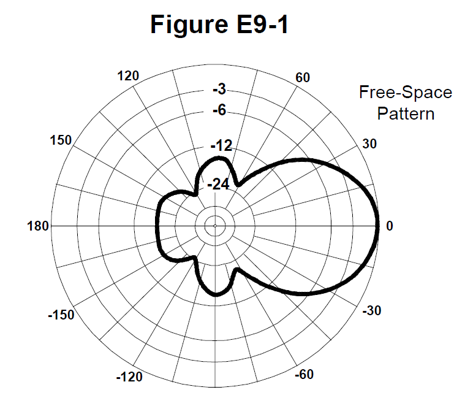
In the antenna radiation pattern shown in Figure E9-1, what is the beamwidth?
A. 75 degrees
B. 50 degrees
C. 25 degrees
D. 30 degrees
You will notice that the heavy line passes through the -3dB line at plus and minus 25 degrees, making the total beamwidth 50 degrees, as in answer B.
E9B02
In the antenna radiation pattern shown in Figure E9-1, what is the front-to-back ratio?
A. 36 dB
B. 18 dB
C. 24 dB
D. 14 dB
You will see that the heavy line at the 180 degree point is mid-way between -12 and -24 dBm, indicating that ratio is 18 dB, answer B.
E9B03
In the antenna radiation pattern shown in Figure E9-1, what is the front-to-side ratio?
A. 12 dB
B. 14 dB
C. 18 dB
D. 24 dB
At the 90 degree points you will notice that the heavy line is at something like -14 dB, making the ratio 14 dB, answer B.
E9B04
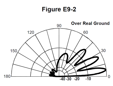
What is the front-to-back ratio of the radiation pattern shown in Figure E9-2?
A. 15 dB
B. 28 dB
C. 3 dB
D. 24 dB
The figure is 28 dB, answer B.
E9B05
What type of antenna pattern over real ground is shown in Figure E9-2?
A. Elevation
B. Azimuth
C. Radiation resistance
D. Polarization
Elevation, answer A.
E9B06
What is the elevation angle of peak response in the antenna radiation pattern shown in Figure E9-2?
A. 45 degrees
B. 75 degrees
C. 7.5 degrees
D. 25 degrees
This is a fairly low angle, 7.5 degrees, answer C.
E9B07
How does the total amount of radiation emitted by a directional gain antenna compare with the total amount of radiation emitted from an isotropic antenna, assuming each is driven by the same amount of power?
A. The total amount of radiation from the directional antenna is increased by the gain of the antenna
B. The total amount of radiation from the directional antenna is stronger by its front-to-back ratio
C. They are the same
D. The radiation from the isotropic antenna is 2.15 dB stronger than that from the directional antenna
Not an ideal question, considering isotropic antennas are impossible, however, imagine it were a simple dipole, and a Yagi, and the answer is that the amount of energy radiated is the same, answer C.
The difference is in the intensity in a certain direction. You can compares this to a room lamp and a car headlamp, which may both use 60 watts, but the reflector and lens of the headlamp generates a much higher intensity of light in one direction.
E9B08
What is the far field of an antenna?
A. The region of the ionosphere where radiated power is not refracted
B. The region where radiated power dissipates over a specified time period
C. The region where radiated field strengths are obstructed by objects of reflection
D. The region where the shape of the antenna pattern is independent of distance
E9B09
What type of computer program technique is commonly used for modeling antennas?
A. Graphical analysis
B. Method of Moments
C. Mutual impedance analysis
D. Calculus differentiation with respect to physical properties
Software such as NEC used Method of Moments, answer B.
E9B10
What is the principle of a Method of Moments analysis?
A. A wire is modeled as a series of segments, each having a uniform value of current
B. A wire is modeled as a single sine-wave current generator
C. A wire is modeled as a series of points, each having a distinct location in space
D. A wire is modeled as a series of segments, each having a distinct value of voltage across it
Each wire (or tube, etc) is modelled as a series of segments, each having a uniform value of current, answer A.
E9B11
What is a disadvantage of decreasing the number of wire segments in an antenna model below the guideline of 10 segments per half-wavelength?
A. Ground conductivity will not be accurately modeled
B. The resulting design will favor radiation of harmonic energy
C. The computed feed point impedance may be incorrect
D. The antenna will become mechanically unstable
This may affect the accuracy of the calculation of the feed point impedance, answer C.
On to: Antennas 2 - Wire & Directional Antennas
You can find links to lots more on the Learning Material page.
Written by Julian Sortland, VK2YJS & AG6LE, September 2022.
Tip Jar: a Jefferson (US$2), A$3 or other amount / currency. Thanks!