
Home - About AR - Learning Material - Exams - Clubs - Posters
This group of 4 pages covers the important topics of antennas and their feedlines. It is followed by a final short page on Safety. You are progressing well!
Remember that you can web search a question number with an appropriate term and potentially get an expalanation.
A theoretical, or rather "hypothetical" or "notional" antenna, used as a reference, is the isotropic radiator, which notionally radiates equally in all directions. No real antenna radiates like this, and in fact, theory tells us that an antenna which radiates linear waves in all directions is not possible. The behaviour could be likened to a light-globe, or to the sun.
They are however a favourite device of the marketing department, as if they describe an antenna's gain relative to a isotropic radiator, rather than a dipole, they can increase the number on their glossy brochure by 2.15 dB.
Many antenna designs concentrate the energy fed into them in a particular direction, while vertical antennas with gain concentrate the signal into a flatter disc. Stacking antennas into arrays can also increase gain. Stacks of halo or other horizontal omni-directional antennas can also flatten the pattern of a horizontal omni signal, and we might use this as a "rover" station in a VHF-UHF contest. This gain is specified in dB, relative to either a dipole or an isotropic radiator.
As we know, a feedline, such as coaxial cable has loss, which can be significant at VHF and UHF, especially if there is some length, such as a feed between a repeater and its antenna(s), even if thicker cable is used. Repeaters typically include duplexers, such as an network of cavity filters; and some include circulators to manage the flow of power, including in the case of an antenna fault. Both of these have some loss, typically listed in dB, and we need to add these together, and to the feedline loss.
One way to consider an antenna systems is to determine the power reaching the feedpoint, being the transmitter power less the losses; then add the gain of the antenna. If 25 watts gets to the antenna, and it has 10 dBd of gain, the effect of the antenna, for stations in the correct location, is that the signal strength is as though a power of 250 watts (10 dB over 25 watts) is fed into a dipole.
I have typically considered the loss and gain, and then applied this to the power of the transmitter.
In any case, the power we calculate is called the ERP, or effective radiated power. This is relative to a dipole, even if asking about gain relative to a dipole has been replaced with ERP in all cases below. In the VHF and UHF broadcasting world (FM radio and TV), licensing is typically for ERP, while for MW and SW (AM), it is for actual power.
On 60 metres where ERP is the rule you can compensate for feedline loss. If you loss was 2 dB then you can put 15 watts into the feedline of of your dipole and have 9.15 watts ERP. 160 watts would give 100 watts ERP. If your antenna is less efficient than a dipole you can use more power.
A variation is the EIRP, a figure 2.15 dB larger than ERP figure. If asking about EIRP then the antenna should be quoted using the salesman's method, in dBi.
One question points out that gain in an antenna is not amplification. If an operator has a 45 watt DMR UHF radio and can switch it between a simple vertical and a long Yagi antenna, the same power is radiated, either though 360 degrees with a fairly wide vertical angle, or in a tight beam. With the beam the signal in other directions is weak.
Note that an antenna may have a gain of 0 dBi. That just means that it is an inefficient antenna, often short or "low profile", but this does not make it an isotropic radiator. An example is this railway antenna:
|
| A UHF train antenna, most likely recovered from a Pacific National locomotive, given the blue. These are bolted through the roof, with the coaxial connected to the N-connector. It likely operated in the 400 to 420 MHz range, so its height of 68 mm makes it very short. Should it contact fallen wires, the energy would hopefully be shorted to the body, and not into the radio. |
Beverage antennas, discussed in the last section, while huge, also have gain below 0 dBi, but were also very quiet, which is what made them useful.
HF antennas on vehicles tend to be inefficient. On middle frequency HF bands an antenna with 0 dBi is a good result.
If we have a simple antenna, such as a dipole or an ordinary vertical (monopole), then as we move away from the resonant frequency the SWR will rise, for example to a point where either the final amplifier is at risk of damage, or protection circuitry winds back the power to protect these stages. With a gain antenna, such as a Yagi, gain may well also drop off outside the design frequency.
A now removed question indicated that the edges of the bandwidth are when an antenna fails to meet its specifications.
Note that if we have a fixed Yagi antenna with a moderate number of elements, it will have moderate gain. It will however have a beamwidth which might take in all the repeaters in a city if we are some distance away. A longer Yagi, with more elements has more gain, but the beamwidth is narrower, so while the signal to and from the repeater in the centre of the beam will be greater, those a little off-axis may receive less signal. Going from perhaps 4 elements to 8 or 10 might result in the behaviour above.
A rough guide to beamwidth is to look at the angle between the points 3 dB down on the signal at the centre of the main lobe on the azimuth plot (the plan view, meaning the view from above). This is not to say that stations beyond that beam will not receive your signal, but too much further outside it, and the S-points will drop.
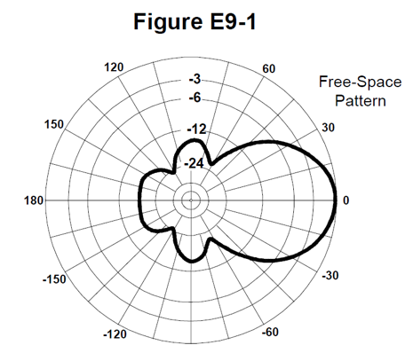
The antenna plotted below has a beamwidth of 50 degrees. The Front to Front-to-Back is 18 dB, and the Front-to-Side ratio is 14 dB. A similar plot can be made with a compass rose to show the pattern of an installed antenna.
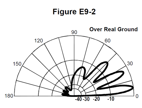
Below is the elevation radiation pattern of a directional antenna. The main lobe has an elevation of 7.5 degrees. Radiation to the rear is 28 dB below that going forward, the front-to-back 28 dB.
These patterns apply both for transmission and reception.
Dish antennas have high to very high gain, and thus have a (very) narrow beamwidth. They are in a question on the next page, using the term "parabolic reflector antenna". There are several ways to feed a dish. The simplest is running a cable to a feedpoint using a simple 2 or 3 element Yagi facing into the dish (small at the operating frequency). This is placed at the Prime Focus. The final RF stages can also be a the is point. Another is to use a horn on the end of waveguide. The Cassegrain and Gregorian systems place a small reflector between the prime focus and the dish which reflects signals from or too a horn in the centre of the dish. All or most apply for both satellite and terrestrial systems, and in radio telescopes and deep space communications systems.
In the past few decades satellite TV has used an oval dish which is a segment of a much larger imaginary round dish. The feed is "offset" and this not in the path of the signal, as with the systems above. They are also used with a range of military and civilian two-way satellite communications systems. They can also be used by Amateurs for contacts between hilltops. Doing this using 5.6 GHz video senders in the place of the Low Noise Block (LNB) used for satellite TV works well, and is both affordable and easy.
You can use a dish at 70 cm, but it needs to be very large (say 6 metres in diameter) and even then has limited gain. They are more effective from 1296 MHz and up. As frequency increases the dish has a greater gain. If you double the frequency the dish becomes twice as many wavelengths high, and twice as many wide. Thus it has 4 times the area to wavelength ratio, and four times the gain. We call this a 6 dB increase in gain.
As frequency increases small dishes become effective. The 6 mm band is 47 GHz, and a dish around 200 mm wide becomes effective. The surface of the dish needs to follow the ideal curve very precisely, and be continuous metal surface. The 6 metre one for UHF can be something like fine chicken wire mesh on a timber frame.
Gain can reach 30 dB, meaning 1 watt fed in can provide the effect of 1 kW in the beam. Gain is also important because received signals can be weak. Satellite TV transponders might cover a third of Australia with one beam, or even the whole of Australia and NZ with one, and they are just a few 10s of watts.
At HF vertical antennas, especially short ones, less than a quarter-wave, require a system of radials for them to provide a reasonable match, and to radiate efficiently. Quarter-wave, 0.28 (100 degree), and five-eighth units also require radials. Even if the vendor claims that their antennas (such as half-waves) don't need a ground-plane or radials, they will likely still be improved by a few radials.
There are several options depending on the type of station. For HF verticals mounted on the ground, several radials of reasonably heavy wire, of a quarter-wave, or five-eighth wire for each band of interest are a good option. For DX-peditions, a large number of fine radials is also an option. Note that the idea of these radials is to provide an RF ground-plane, NOT for lightning protection. That said, the radial should be bonded to the grounding system.
In another case of adding a topic by adding a single question, the band with the smallest First Fresnel zone is asked for. However, I think it can be handled by an overarching principle that of wavelength being inversely proportional to the frequency. Of the offered answers, 5.8 GHz has the shortest wavelength, just over 5 cm, this being the name of the band.
The first Fresnel zone is a blimp shaped region which exists for the path between the stations, especially in UHF and microwave spectrum. If there is an obstruction in this zone the signal is weakened. 20% of the area being obstructed is considered acceptable, over 40% is significant. This can cause noise on a voice signal or packet loss on a digital signal.
It is named for Augustin-Jean Fresnel, a French civil engineer and physicist, also known for the Fresnel Lens for lighthouses, which helped save a huge number of lives.
Say you are sharing Internet access with your neighbour a few hundred metres away across a rural road, and you have antennas just above the height of the highest trucks. With a laser system this would be fine, but if you used 2.4 GHz Wi-Fi and directional antennas trucks are going to pass through the Fresnel zone, as calculated below. This will cause errors and the need to retransmit some packets when each truck passes. An SUV may cause some disruption, but a car likely passes under it, or through only the very lowest part.
At the centre of the path the radius = 8.656 × √(D / 𝑓) where the radius is in metres, Distance between stations is in kilometres, and 𝑓 is in GHz.
r = 8.656 × √(0.3 / 2.4) = 8.656 × √(0.125) = 8.656 × 0.353553390593274 = 3.060 metres
For 5.8 GHz: r = 8.656 × √(0.3 / 5.8) = 8.656 × √(0.0517241379310345) = 8.656 × 0.227429413073671 = 1.969 metres
For smelly feet and English miles the factor is 36.03.
To reiterate the first paragraph, the derivation of the above formula places λ (wavelength) on the top of fractions, meaning size (radius) grows with wavelength. One step is r = ½ √(λ × D), using metres in all parts. Using λ = 0.124875 metres at 300 metres also gets a 3.060 metre radius.
One of the right wing "Liberal" Party's alternatives to Labor's pure fibre NBN was placing fixed wireless into lower income areas of my town instead. Installed by untrained contractors using instructions from non-competent managers, they were installed pointing at the nearest tower, not the one with the clearest path. Thus many were installed with trees likely not only in the Fresnel zone, but in the direct path. Of course wet foliage attenuates microwave signals. Either way, at 3.5 GHz and 2.39 km the radius is:
r = 8.656 × √(2.39 / 3.5) = 8.656 × √(0.682857142857143) = 8.656 × 0.826351706513118 = 7.153 metres
Note that between a repeater or TV transmitter and each listener or viewer such a zone exists. Terrain can also fall in the Fresnel zone, be it a hill between the stations, or just flat ground between two antennas with insufficient height.
Click on the diagrams to expand them: Wikipedia: Fresnel zone
When placing antennas on a mast on a mountain many feel that the UHF antennas should be above the VHF. However, potential interaction with the immediate terain, such as a slow initial fall-off may mean that a VHF antenna placed close to the ground interacts with ground. Thus it may be beneficial to have the VHF above the UHF. This is a case of close-in Fresnel Zones causing "aperture blocking" at lower frequencies.
If you share an Internet connection across a joint boundary optical fibre is likely the best option, as it provides high speed and full electrical isolation. Ethernet has transformers, which is OK for anomalies relating to mains power or DC traction systems (trains or trams), but not lightning.
This is the value of a resistance that would dissipate the same amount of power as is radiated by the antenna.
When we use an antenna to couple RF energy from a feedline to free space, there is an effective resistance, which can be calculated. This is in addition to ohmic losses, caused by the resistance of the conductor, say if we used thin stainless steel wire for an long low-HF antenna. Given P = I²R, we can determine this via R = P/I², although I suppose that this is taking in the usually small ohmic resistance too.
Antenna efficiency is the radiation resistance divided by total resistance.
More on Wikipedia: Radiation resistance
There are a range of antenna modelling systems, some for specific formats, and some more general. These can tell the user many things about the proposed antenna, including impedance related parameters, including SWR vs frequency charts; polar plots of the far field elevation and azimuth patterns which can provide information including front-to-back and front-to side ratios; and antenna gain. Some systems can run through a range of optimisations, such as element spacing in a yagi. NEC is a famous example, standing for "Numerical Electromagnetics Code". It was developed by the Lawrence Livermore National Laboratory in California, a US Government Agency, and thus certain versions are available in the public domain.
NEC uses the method of moments. While the calculation method is discussed, NEC is no longer named. If less than 10 segments per half-wavelength are used in calculations then the input impedance can be incorrectly calculated. I suppose the only reason someone would do this is to increase calculation speed, likely unnecessary with a modern PC.
The NEC engine is packaged with a graphical user interface, one example being 4nec2, available at: www.qsl.net/4nec2/
This is not the National Electrical Code, the safety standard for power systems in the US. It is also unrelated to the once great Japanese microwave (comms and ovens) and IT company which now can't even successfully implement a bus ticketing system for Canberra.
It is important to realise that an antenna can give an SWR reading of 2:1, or significantly higher, and still be resonant, if its impedance is other than 50 ohms (assuming that is the impedance of our system). I rather like my delta loop (on 6 metres), but these have an impedance of 102 ohms, or thereabouts. While we could use 50 ohm coax, and a tuner, which some authors do suggest, there are other methods, such as using a quarter-wave section of coax as a matching section. Other antennas may have am impedance of 200, 300, or 450 ohms, or more. In such cases a balun or unun is used to match to coax, such as 50 ohm coax.
These are actual questions from the NCVEC Extra exam pool for mid-2024 to mid-2028.
E9A01
What is an isotropic radiator?
A. A calibrated, unidirectional antenna used to make precise antenna gain measurements
B. An omnidirectional, horizontally polarized, precisely calibrated antenna used to make field measurements of antenna gain
C. A hypothetical, lossless antenna having equal radiation intensity in all directions used as a reference for antenna gain
D. A spacecraft antenna used to direct signals toward Earth
This is an imaginary antenna, to which a the gain of a real antenna can be referenced, answer C.
E9A02
What is the effective radiated power (ERP) of a repeater station with 150 watts transmitter power output, 2 dB feed line loss, 2.2 dB duplexer loss, and 7 dBd antenna gain?
A. 469 watts
B. 78.7 watts
C. 420 watts
D. 286 watts
Subtracting the total loss of 4.2 dB from the 7 dB gain we get 2.8 dB gain. We know that if we added 3 dB to 150 watts we would get 300 watts. 286 watts is a little less than this, and so answer D is the only viable one.
From an online calculator, +2.8 dB is a multiplication in power of 1.91. 150 × 1.91 = 286.5 watts.
E9A03
What term describing total radiated power takes into account all gains and losses?
A. Power factor
B. Half-power bandwidth
C. Effective radiated power
D. Apparent power
If we take the transmitter power, then take into account losses in the feedline, and any filters, etc, and then the gain of the antenna, we get the effective radiated power, answer C.
E9A04
Which of the following factors may affect the feed point impedance of an antenna?
A. Transmission line length
B. Antenna height
C. The settings of an antenna tuner at the transmitter
D. The input power level
This asks about the feedpoint of the antenna, not external factors, and the only one discussing the actual antenna is answer B.
This most strongly affects horizontal HF wire antennas above a conductive ground or other surface.
E9A05
What does the term "ground gain" mean?
A. The change in signal strength caused by grounding the antenna
B. The gain of the antenna with respect to a dipole at ground level
C. To force net gain to 0 dB by grounding part of the antenna
D. An increase in signal strength from ground reflections in the environment of the antenna
A signal may bounce of the ground in front of (or around) an antenna, and his can increase the strength of the signal at the receiver, answer D.
E9A06
What is the effective radiated power (ERP) of a repeater station with 200 watts transmitter power output, 4 dB feed line loss, 3.2 dB duplexer loss, 0.8 dB circulator loss, and 10 dBd antenna gain?
A. 317 watts
B. 2,000 watts
C. 126 watts
D. 300 watts
Losses of 8 dB, and gain of 10 dB in the antenna calculates as: 10 - (4 + 3.2 + 0.8) = 10 - 8 = 2 dB. This gives 317 watts, answer A.
Adding 1 or 2 dB results in a non-round number. More interesting is a pattern I have noticed: While film at K-Mart came in 100, 200, 400 ASA (whole stops), if you went to an enthusiast or professional shop you could get 25 Kodachrome, 32 B&W, 40 Super 8 movie, 50 E6 slide, 64 Kodachrome, 80 ORTHO Plus*, 100, 125 B&W, and 160 colour negative for portraits, stepping up mostly in one-third stops. Better digital SLRs also do this, with ISO settings including 200, 250, 320, and 400. Stepping up 1, 2, and 3 dB above 200 watts gives us 252, 317, and 400 watts, very close to the film speeds, which may be rounded for simplicity, or for consistency, such as with 32 and 3200 (the latter reached by successive multiplication from 100).
* A new film from Ilford.
E9A07
What is the effective isotropic radiated power (EIRP) of a repeater station with 200 watts transmitter power output, 2 dB feed line loss, 2.8 dB duplexer loss, 1.2 dB circulator loss, and 7 dBi antenna gain?
A. 159 watts
B. 252 watts
C. 632 watts
D. 63.2 watts
Losses are 2 + 2.8 + 1.2 dB, totalling 6 dB; and gain is 7 dBi, so over-all gain is 1 dB, and 1 dB over 200 watts can only be 252 watts, so it is answer B.
E9A08
Which frequency band has the smallest first Fresnel zone?
A. 5.8 GHz
B. 3.4 GHz
C. 2.4 GHz
D. 900 MHz
The smaller the wavelength (or higher the frequency) the smaller the first Fresnel zone, so 5.8 GHz, answer A.
E9A09
What is antenna efficiency?
A. Radiation resistance divided by transmission resistance
B. Radiation resistance divided by total resistance
C. Total resistance divided by radiation resistance
D. Effective radiated power divided by transmitter output
To get the efficiency divide radiation resistance by total resistance, answer B.
E9A10
Which of the following improves the efficiency of a ground-mounted quarter-wave vertical antenna?
A. Installing a radial system
B. Isolating the coax shield from ground
C. Shortening the radiating element
D. All these choices are correct
Most would say radials are essential for a quarter-wave antenna system, answer A.
E9A11
Which of the following determines ground losses for a ground-mounted vertical antenna operating on HF?
A. The standing wave ratio
B. Distance from the transmitter
C. Soil conductivity
D. Take-off angle
Often losses are the result of resistance, the inverse of conductivity, so it is reasonable to link this soil conductivity (or lack thereof) to ground losses, answer C.
E9A12
How much gain does an antenna have compared to a half-wavelength dipole if it has 6 dB gain over an isotropic radiator?
A. 3.85 dB
B. 6.0 dB
C. 8.15 dB
D. 2.79 dB
dBi is the marketers' number, so the dBd figure is less impressive, or lower, by 2.15 dB, so 6 - 2.15 = 3.85 dBd, answer A.
E9B01
What is the 3 dB beamwidth of the antenna radiation pattern shown in Figure E9-1?
A. 75 degrees
B. 50 degrees
C. 25 degrees
D. 30 degrees
You will notice that the heavy line passes through the -3dB line at plus and minus 25 degrees, making the total beamwidth 50 degrees, as in answer B.
E9B02
What is the front-to-back ratio of the antenna radiation pattern shown in Figure E9-1?
A. 36 dB
B. 14 dB
C. 24 dB
D. 18 dB
You will see that the heavy line at the 180 degree point is mid-way between -12 and -24 dBm, indicating that ratio is 18 dB, answer D.
E9B03
What is the front-to-side ratio of the antenna radiation pattern shown in Figure E9-1?
A. 12 dB
B. 24 dB
C. 18 dB
D. 14 dB
At the 90 degree points you will notice that the heavy line is at something like -14 dB, making the ratio 14 dB, answer D.
E9B04
What is the front-to-back ratio of the radiation pattern shown in Figure E92?
A. 15 dB
B. 28 dB
C. 3 dB
D. 38 dB
The figure is 28 dB, answer B.
Clearly they mean "Figure E9-2", so it may be presented as above, or a VE or VEC may correct it.
E9B05
What type of antenna pattern is shown in Figure E9-2?
A. Elevation
B. Azimuth
C. Near field
D. Polarization
The base line represents the ground, and the numbers the elevation, answer A.
E9B06
What is the elevation angle of peak response in the antenna radiation pattern shown in Figure E9-2?
A. 45 degrees
B. 75 degrees
C. 7.5 degrees
D. 25 degrees
This is a fairly low angle, 7.5 degrees, answer C.
E9B07
What is the difference in radiated power between a lossless antenna with gain and an isotropic radiator driven by the same power?
A. The power radiated from the directional antenna is increased by the gain of the antenna
B. The power radiated from the directional antenna is stronger by its front-to-back ratio
C. They are the same
D. The power radiated from the isotropic radiator is 2.15 dB greater than that from the directional antenna
Not an ideal question, considering isotropic antennas are impossible, however, imagine it were a simple dipole, and a Yagi, and the answer is that the amount of energy radiated is the same, answer C.
The difference is in the intensity in a certain direction. You can compares this to a room lamp and a car headlamp, which may both use 60 watts, but the reflector and lens of the headlamp generates a much higher intensity of light in one direction.
E9B08
What is the far field of an antenna?
A. The region of the ionosphere where radiated power is not refracted
B. The region where radiated power dissipates over a specified time period
C. The region where radiated field strengths are constant
D. The region where the shape of the radiation pattern no longer varies with distance
E9B09
What type of analysis is commonly used for modeling antennas?
A. Graphical analysis
B. Method of Moments
C. Mutual impedance analysis
D. Calculus differentiation with respect to physical properties
The is Method of Moments, answer B.
Software such as NEC (Numerical Electromagnetics Code) uses this.
E9B10
What is the principle of a Method of Moments analysis?
A. A wire is modeled as a series of segments, each having a uniform value of current
B. A wire is modeled as a single sine-wave current generator
C. A wire is modeled as a single sine-wave voltage source
D. A wire is modeled as a series of segments, each having a distinct value of voltage across it
Each wire (or tube, etc) is modelled as a series of segments, each having a uniform value of current, answer A.
E9B11
What is a disadvantage of decreasing the number of wire segments in an antenna model below 10 segments per half-wavelength?
A. Ground conductivity will not be accurately modeled
B. The resulting design will favor radiation of harmonic energy
C. The computed feed point impedance may be incorrect
D. The antenna will become mechanically unstable
This may affect the accuracy of the calculation of the feed point impedance, answer C.
A directional antenna not discussed, but useful for things links between repeaters or agency "remote base" stations is the corner reflector: ⋖ For UHF or VHF they can be mounted on a tower, and be vertical or horizontally polarised. Wikipedia: Corner reflector antenna also shows a ground-mounted vertical one for HF.
A certain state-wide revenue raising agency in NSW had one feeding the agency radio system from a base in one town to one another further north, with a licensed power of 1 watt, but wanted to feed additional towns to the NE and NW, outside the main lobes. Instead of designing and licensing a proper, legal system they just cranked the power to 30 watts. The radio agency found out, and fined the donut consuming folks, due to the potential for interference, etc. As you can see in Figure R9-1 above, at around 50 degrees off the beam 12 dB more power is needed to get a similar signal at the other end.
A cartoon in a magazine from the UK, where gain antennas on 27 MHz CB were illegal, showed what I suppose was a helical antenna mounted at the corner of an old hen or bird cage, with only the two panels away from the antenna present, along with a frowning Radio Inspector, and the owner making an excuse. However the antenna should be closer to the centre of the implied square; perhaps it was.
These are different to passive corner reflectors which can reflect radar signals from a small mostly non-metal boat, or a balloon. A single diamond shaped unit with sectors is the option. Apparently the slim, round versions with a stack of discs / disks with right angle elements between them close to useless. A large bank of glass ones have been left on the moon by Apollo programme, each element similar to a surveyor's target; the Soviet Lunokhod (Луноход, or "Moonwalker") remote controlled lunar rover (the first remote rover) has a small bank of these. A high power laser can be used to measure the distance to the moon via these. The Apollo ones are not exactly square, so they reflect light to where the telescope will be once the light returns to earth. See: Wikipedia: Corner reflector
On to: Antennas 2 - Wire & Directional Antennas
You can find links to lots more on the Learning Material page.
Written by Julian Sortland, VK2YJS & AG6LE, February 2026.
Tip Jar: a Jefferson (US$2), A$3, GB£3 or other amount / currency. Thanks!
You can also buy me a non-coffee beverage: ko-fi.com/ag6le