Home - About AR - Learning Material - Exams - Clubs - Posters
Below a range of antennas for reception are discussed.
The Smith chart has a specific purpose: To determine the resistance and reactance along a feedline, and thus the impedance. SWR can also be determined.
Below is the examiner's representation of the Smith chart, somewhat simplified, but for some strange reason, rotated 90 degrees, so that the infinity point is at the bottom, rather than the right side.
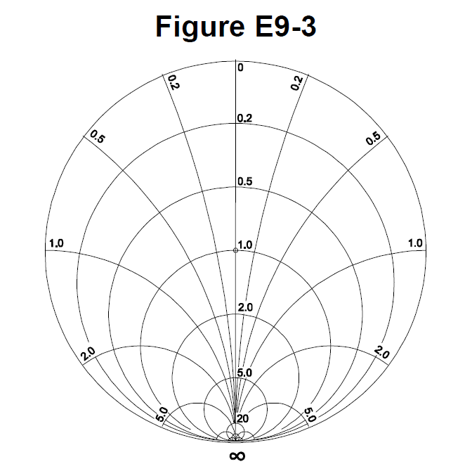
The central line is resistance, ranging from infinity to zero. One at the centre refers to the system impedance, which can be "normalised" to a value such as 50 ohms. The circles which cross this line are the "resistance circles". The arcs are the "reactance arcs".
Anything to do with antenna patterns, propagation, radiation resistance, satellites, or trigonometry etc, is false.
They were invented by Phillip H. Smith, while at Bell Labs. He was working on feedlines and arrays of HF antennas designed for communications with Europe and South America, and needed a better system to understand the standing waves on the line.
I suggest reading the article, Wikipedia: Smith Chart
It was also invented independently by Mizuhashi Tosaku in Japan.
A Beverage antenna is not one made from beer cans, but a very long wire antenna for receiving long-wave and medium-wave signals. They are basically built like a telegraph line, and are at least a wavelength long, terminated via a resistor to ground at the far end. They are directional, with signals travelling from the far end of the antenna.
They are useful for 160 metre reception, and for MW DXing. They were originally used for trans-Atlantic telephone circuits, and often with several in parallel.
There is a useful animation on Wikipedia: Beverage Antenna.
There are a range of loop antenna configurations, but the question refers to receiving unit, especially popular in the past. These consist of an X-shaped frame, forming a square with perhaps a ten to a dozen turns of wire. An indoor one for DX might be 750 mm on each side, but one on the back of an old (well, 1990s) AM-stereo receiver I have is has a 10 cm high by 20 cm loop, while Wikipedia shows an octagonal one 2.7 metres in diameter. In all cases, these are "small", being significantly smaller than a wavelength in perimeter. These antennas are directional, with strongest signals broadside to the loop, and a null to the sides.
To increase gain it is necessary to either increase the diameter of the loop, or the number of turns on the loop.
Portable versions, around 200 mm in diameter, can be used as part of an HF direction finding, but have disadvantage that there are two nulls, so it is necessary to take readings in at least two positions, and triangulate the approximate position. Adding a "sense" antenna can modify the pattern, so a single null can be detected.
This is a triangular loop, in the shape of a pennant. The typical rear piece is 4 to 5 metres high, with the coax connected to the centre of this wire. From the tips, the wires go forward for 8 to 10 metres, to a point. At the point a 900 (or 910) ohm resistor is fitted, to "terminate" the antenna. These work well for 160 and 80 metre reception. The point should face the transmitting station.
These are actual questions from the NCVEC Extra exam pool.
E9G01
Which of the following can be calculated using a Smith chart?
A. Impedance along transmission lines
B. Radiation resistance
C. Antenna radiation pattern
D. Radio propagation
Impedance along transmission lines, answer A.
E9G02
What type of coordinate system is used in a Smith chart?
A. Voltage circles and current arcs
B. Resistance circles and reactance arcs
C. Voltage lines and current chords
D. Resistance lines and reactance chords
Resistance circles and reactance arcs, answer B.
E9G03
Which of the following is often determined using a Smith chart?
A. Beam headings and radiation patterns
B. Satellite azimuth and elevation bearings
C. Impedance and SWR values in transmission lines
D. Trigonometric functions
Impedance and SWR values in transmission lines, answer C.
E9G04
What are the two families of circles and arcs that make up a Smith chart?
A. Resistance and voltage
B. Reactance and voltage
C. Resistance and reactance
D. Voltage and impedance
Resistance and reactance, answer C.
E9G05
Which of the following is a common use for a Smith chart?
A. Determine the length and position of an impedance matching stub
B. Determine the impedance of a transmission line, given the physical dimensions
C. Determine the gain of an antenna given the physical and electrical parameters
D. Determine the loss/100 feet of a transmission line, given the velocity factor and conductor materials
The Smith Chart Can be used to determine the length and position of an impedance matching stub, answer A.
E9G06
On the Smith chart shown in Figure E9-3, what is the name for the large outer circle on which the reactance arcs terminate?
A. Prime axis
B. Reactance axis
C. Impedance axis
D. Polar axis
This is the reactance axis, answer B.
E9G07
On the Smith chart shown in Figure E9-3, what is the only straight line shown?
A. The reactance axis
B. The current axis
C. The voltage axis
D. The resistance axis
This is the resistance axis, answer D.
E9G08
What is the process of normalization with regard to a Smith chart?
A. Reassigning resistance values with regard to the reactance axis
B. Reassigning reactance values with regard to the resistance axis
C. Reassigning impedance values with regard to the prime center
D. Reassigning prime center with regard to the reactance axis
Reassigning impedance values with regard to the prime centre, answer C.
E9G09
What third family of circles is often added to a Smith chart during the process of solving problems?
A. Standing wave ratio circles
B. Antenna-length circles
C. Coaxial-length circles
D. Radiation-pattern circles
These are standing wave ratio circles, answer A.
E9G10
What do the arcs on a Smith chart represent?
A. Frequency
B. SWR
C. Points with constant resistance
D. Points with constant reactance
Thes are with constant reactance, answer D.
Any point along the the 0.5 arc means a reactance of half the characteristic impedance, so a reactance typically of 25 ohms.
E9G11
How are the wavelength scales on a Smith chart calibrated?
A. In fractions of transmission line electrical frequency
B. In fractions of transmission line electrical wavelength
C. In fractions of antenna electrical wavelength
D. In fractions of antenna electrical frequency
These are fractions of transmission line electrical wavelength, answer B.
E9H01
When constructing a Beverage antenna, which of the following factors should be included in the design to achieve good performance at the desired frequency?
A. Its overall length must not exceed 1/4 wavelength
B. It must be mounted more than 1 wavelength above ground
C. It should be configured as a four-sided loop
D. It should be one or more wavelengths long
It must be one or more wavelengths long, answer D.
E9H02
Which is generally true for low band (160 meter and 80 meter) receiving antennas?
A. Atmospheric noise is so high that gain over a dipole is not important
B. They must be erected at least 1/2 wavelength above the ground to attain good directivity
C. Low loss coax transmission line is essential for good performance
D. All of these choices are correct
Atmospheric noise is so high that antenna gain is not particularly important, answer A.
E9H03
What is Receiving Directivity Factor (RDF)?
A. Forward gain compared to the gain in the reverse direction
B. Relative directivity compared to isotropic
C. Relative directivity compared to a dipole
D. Forward gain compared to average gain over the entire hemisphere
This is forward gain compared to average gain over the entire hemisphere, answer D.
E9H04
What is an advantage of placing a grounded electrostatic shield around a small loop direction-finding antenna?
A. It adds capacitive loading, increasing the bandwidth of the antenna
B. It eliminates unbalanced capacitive coupling to the surroundings, improving the nulls
C. It eliminates tracking errors caused by strong out-of-band signals
D. It increases signal strength by providing a better match to the feed line
This eliminates unbalanced capacitive coupling to the surroundings, improving the nulls, answer B.
E9H05
What is the main drawback of a wire-loop antenna for direction finding?
A. It has a bidirectional pattern
B. It has no clearly defined null
C. It is practical for use only on VHF and higher bands
D. All these choices are correct
This antenna has a bidirectional pattern, answer A.
E9H06
What is the triangulation method of direction finding?
A. The geometric angles of sky waves from the source are used to determine its position
B. A fixed receiving station plots three headings to the signal source
C. Antenna headings from several different receiving locations are used to locate the signal source
D. A fixed receiving station uses three different antennas to plot the location of the signal source
Headings are taken from two or more locations to determine the location of the transmitter or interference source, answer C.
E9H07
Why is RF attenuation used when direction-finding?
A. To narrow the receiver bandwidth
B. To compensate for isotropic directivity and the antenna effect of feed lines
C. To increase receiver sensitivity
D. To prevent receiver overload which reduces pattern nulls
This helps to prevent receiver overload, which reduces pattern nulls, answer D.
E9H08
What is the function of a sense antenna?
A. It modifies the pattern of a DF antenna array to provide a null in one direction
B. It increases the sensitivity of a DF antenna array
C. It allows DF antennas to receive signals at different vertical angles
D. It provides diversity reception that cancels multipath signals
This provides a null in one direction, answer A.
E9H09
What is a Pennant antenna?
A. A four-element, high-gain vertical array invented by George Pennant
B. A small, vertically oriented receiving antenna consisting of a triangular loop terminated in approximately 900 ohms
C. A form of rhombic antenna terminated in a variable capacitor to provide frequency diversity
D. A stealth antenna built to look like a flagpole
This is a small, vertically oriented receiving antenna consisting of a terminated triangular loop, answer B.
E9H10
How can the output voltage of a multiple-turn receiving loop antenna be increased?
A. By reducing the permeability of the loop shield
B. By utilizing high impedance wire for the coupling loop
C. By winding adjacent turns in opposing directions
D. By increasing the number of turns and/or the area
You can increase the number of turns, or you can increase the area of the loop, answer D.
E9H11
What characteristic of a cardioid pattern antenna is useful for direction finding?
A. A very sharp peak
B. A very sharp single null
C. Broadband response
D. High radiation angle
These have a single very sharp null, answer B.
On to: Safety - Earthing, RF hazards & Hazardous materials
You can find links to lots more on the Learning Material page.
Written by Julian Sortland, VK2YJS & AG6LE, September 2022.
Tip Jar: a Jefferson (US$2), A$3 or other amount / currency. Thanks!