Home - About AR - Learning Material - Exams - Clubs - Posters - EVs
A range of antennas generally used for reception are discussed below, but first a system designed to assist in calculating antenna matching.
With the new QRP addition to 60 metres a gain receiving antenna may be more useful on this band. A Beverage of 95 to 120 metres should work well, longer is OK too.
The Smith chart has a specific purpose: To determine the resistance and reactance along a feedline, and thus the impedance. SWR can also be determined. This applies to transmitting antennas, as well as receiving.
Below is the examiner's representation of the Smith chart, somewhat simplified. It has been corrected to have the infinity point on the right side.
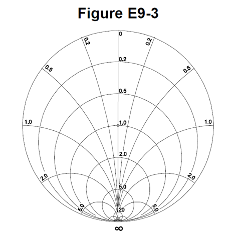
The central line, the only straight one, is resistance, ranging from infinity to zero. The 1.0 at the centre refers to the system impedance, which can be "normalised" to a value such as 50 ohms. This is generally where we want an antenna system to be, as it is the 1:1 SWR point.
The circles which cross this line are the "resistance circles". The arcs are the "reactance arcs". A resonant delta antenna would be on the centre line at 2.01, being 102 / 50. An inductive component, with a +j component would be on the upper part, along a arc. A capacitive one with a -j component would be on the lower part.
They were originally designed to be used on paper, but are also a display option on a VNA or Nano-VNA.
Rohde & Schwarz, manufacturer of RF test equipment has a tutorial: Vector network analyzer fundamentals - Understanding the Smith chart. It has a colour-coded chart which shows that inductive values exist on the upper section, capacitive on the lower, and resistive in the centre. It also shows this is in common with the Cartesian coordinates discussed quite a few pages ago on here. Each chart can be clicked on to enlarge.
They normalise for 50 Ω, but if you were designing a TV receive antenna, or working on some TV broadcast systems, this would be 75 Ω.
A VNA can do a run of frequencies and present it as a curved line, as on the dull green line on the R&S page above. If our WICEN / RACES / ARES group had been gifted or transferred an airside service vehicle from a coastal airport, the VHF Air antenna would have a have a plot passing close to or through the 1.0 point at around 120 MHz, and be inductive at 2 metres. The antenna for liaising with rescue boats passes 1.0 at around 160 MHz, and is capacitive at 2 metres. An antenna cut for an emergency frequencies such as 468.575 MHz may be capacitive (negative j) on 70 cm. (By the way that is ESO Air 1, an aviation liaison channel available to all agencies in NSW using type-approved equipment). At UHF bandwidth can be quite broad. Over a wide range resonance at harmonics may be evident, or perhaps the frequency at which a quarterwave antenna is a 5/8.
Anything to do with antenna patterns, propagation, radiation resistance, satellites, or trigonometry etc, is false. Also reactance values are importannt, NOT the value of the inductance or capacitance itself.
They were invented by Phillip H. Smith, while at Bell Labs, just before WW2. He was working on feedlines and arrays of HF antennas designed for communications with Europe and South America, and needed a better system to understand the standing waves on the line.
I suggest reading the article: Wikipedia: Smith Chart
It was also invented independently by Mizuhashi Tosaku in Japan, and by Amiel R. Volpert (Амиэ́ль Р. Во́льперт).
A Beverage antenna is not one made from beer cans, but a very long wire antenna for receiving long-wave and medium-wave signals. They are basically built like a telegraph line, and are at least a wavelength long, terminated via a resistor to ground at the far end. They are directional, with signals travelling from the far end of the antenna. 450 ohms in typical, and something like an old engine block can be a good earth, or a couple of short ground rods or surplus copper pipe. Radials may be added.
The examiner needs you to know that the "correct" resistor value is found then there is a minimum variation in SWR over the desired frequency range. While a non-inductive variable resistor can be used to find the value, an option is to measure its value and replace it with a combination of fixed ones which match this value. Carbon composition, thick film, or other non-inductive resistors, perhaps the KOA Speer Ceramic Composition Resistors, are the better choice. Some are advertised as "anti-pulse" or "anti-surge", and suitable for switchmode power supplies. Pulse / surge resistant might be a better term, and while they would not survive a direct lightning strike, they should tolerate induced energy.
"Long" means that they often need hundreds of metres to over a kilometre. Historical examples were even longer, used for radio circuits in transatlantic telephone systems. There is no reason land under them could not be used for grazing or cropping, as long as you avoid having equipment catching the wire. One below is shown in a field of what looks like Brassicas. Maybe 72 metres for YO8RXP's 1.7 wavelength jobbie on 40 metres would work too.
These are a travelling-wave antenna, which means the signal builds as it travels from the terminated end to the receiver. Unwanted signals from the rear are absorbed by the terminating resistor.
Further reading: Wikipedia: Beverage antenna, QST: The Beverage Antenna - 100 Years Later (PDF), and Making it up: Beverage Antenna Enables Intercontinental MW Listening.
Off the exam, there is an option to build it using two wires placed in a way they form a parallel transmission line, and via transformers make it work in the reverse direction, and act as its own feedline. Relays can make it reversible. VE3VN has even made one from RG6 coax.
The impedance is 450 Ω so a transformer is required. FairRite Products 2873000202 "binocular" core using 73-mix is suitable. I'd suggest 75 Ω coax, and thus 5 turns on the primary, and two on the secondary. The other side of the primary is connected to a ground rod or similar. If using 50 ohm cable is used a 6:2 ratio is needed. The core is 14-15 mm long. They are a little over a dollar each at MiniKits, or 5 for A$6.80 at RS.
The examiner ignores 630 and 2200 metres, along with the newly expanded 60 metres, but these antennas would work here, and any other band in this spectrum. In Australia the primary use for frequencies below the AM broadcast band (LW or LF) is airport "terminal information", carrying weather and runways in use, and non-directional beacons with Morse IDs (tones on AM signals).
You can buy me a V or other beverage.
There are a range of loop antenna configurations, but the question refers to receiving unit, especially popular in the past. These consist of an X-shaped frame, forming a square with perhaps a ten to a dozen turns of wire. An indoor one for DX might be 750 mm on each side, but one on the back of an old (well, 1990s) AM-stereo receiver I have is has a 10 cm high by 20 cm loop, while Wikipedia shows an octagonal one 2.7 metres in diameter. In all cases, these are "small", being significantly smaller than a wavelength in perimeter. These antennas are directional, with strongest signals broadside to the loop, and a null to the sides.
To increase gain it is necessary to either increase the diameter of the loop, or the number of turns on the loop.
Portable versions, around 200 mm in diameter, can be used as part of an HF direction finding, but have disadvantage that there are two nulls, so it is necessary to take readings in at least two positions, and triangulate the approximate position. Adding a "sense" antenna can modify the pattern, so a single null can be detected.
Off the exam, regular sized ferrite rod antennas inside home or portable AM / MW radios have a fairly broad angle over which they receive signals, broadside to the rod; and a tight null end-on, which can he used to reduce the level of an interfering station or noise source.
QEX, ARRL's more technical magazine, also published a design for a monster version, consisting of 14 × 9 or 10 mm rods glued together, 7 in a hexagonal form by 2 rods long, ideally around 300-400 mm in total. Perhaps with a lining material (plastic or paper) a single layer closely wound coil of enamelled wire was wound over it. This assembly was mounted horizontally to sit on a table or desk, with the ability to rotate it.
This is a useful for receiving. This is a triangular loop, in the shape of a pennant. The typical rear piece is 4 to 5 metres high, with the coax connected to the centre of this wire. From the top and bottom, the wires go forward for 8 to 10 metres, to a point. At the point a 900 (or 910) ohm resistor is fitted, to "terminate" the antenna. These work well for 160 and 80 metre reception, ditto 40 m, and for medium wave AM DXing. It should thus work on 60 metres, and the "tropical" bands such as 120 metres. The point should face the transmitting station. The examiner indicates that it is a small, vertically oriented "single-turn, terminated loop". It is "important" that you know it has a Cardioid pattern.
The feedpoint impedance is of the order of 850 to 900 ohms. Thus a transformer is needed. They can use 75 ohm coax, or 50 ohms. A pre-amplifier is also a very good idea, as with the Beverage.
The cardioid is mostly round pattern, with the exception of a null at the rear. The pattern applies to many microphones too. To see the shape: Wikipedia: Cardioid
K6SE wrote a QST article, reporting in a design by Jose EA3VY with the whole metre dimensions converted to decimal feet. A 3 metre vertical section with the top and bottom wires meet at a point 15 m away, the bottom 1 metre (3.28 ft) above ground, and a 725 Ω terminating resistor at the point. It had a F:B of 23 dB on 160 metres, with a cardioid azimuth pattern. A design he developed (hence the smelly feet) had a 14 ft vertical section, 29 ft horizontal dimension, and 6 ft elevation, with a 903 Ω termination-resistor. The feedpoint impedance was 860 Ω.
Apparently two can be placed 50 to 100 metres apart, as discussed here: KD9SV Pennant Antenna. It is no longer listed for sale on the site. You likely need to ensure that the feedlines the same type and length to ensure correct phasing, assuming the antennas point at the transmitter with reasonably good accuracy.
80 and 160 metres are often referred to as the "low bands" as for many years they were the lowest frequency amateur bands. However 160 metres, with until recently the longest bandwidth, is also "Top Band".
Especially on 160 metres operators often use more than one antenna. A top loaded mast or tower can be used for transmitting, and various wire antennas such as slopers can be used for reception (and transmission). A Pennant or Flag can be used for Rx. If a large amount of land is available a Beverage may be used. Dipoles are not particularly popular, but an option if you have the land. Depending on the radio or tuner you can always do a check on reception on the transmitting antenna. Transcontinental or trans-Tasman contacts may be reasonably common, but trans-Pacific is serious DX, and a lot less common on this band. FT8 may be increasing DX contacts, but this likely still relies on grey-line or night-time / early morning operation.
If you have a tower consisting of 3 or 4 vertical legs, such as with a beam on top there are various options to shunt feed it. One option is a cage of 3 or 4 wires mirroring the legs, perhaps 60 cm away from it. A good system of radials is required.
While a "blast from the past" cage dipoles are a good option for 80 metres, and for "75 meters", as some Americans call the voice portion towards 4 MHz; and no doubt shorter bands.
Higher priced MF/HF radios have a receive antenna input (potentially an RCA). Some tuners have an antenna change-over relay which can be operated via a press button, etc.
There are many books and web pages with designs, such as: DJ0IP: 160 metre Inverted L on a 22 wire antennas for 160, and N9NB & W5JAW: Use your Tower for 75/80 and 160 Meters. There are also many selling prepared antennas for home or portable use, including Ni4L, TECSUN Ultra-Portable HF Vertical Antenna, and ZCG (Australia). Another is wireantennas.co.uk, which doesn't allow you to block cookies.
A sloper on mid-upper HF is often a centre-fed half-wave dipole. Especially at longer wavelengths it can be a single wire, fed at ground level against an RF ground, or fed at the top of a tower, water tower, or other structure, with the braid connected to that structure.
An inverted-V is another option, across a wide range of frequencies, using a single centre support, and shorter supports at the ends. Well, unless it is made from two wires off a short piece of thin solid coax; 54.9 mm elements for 1296 MHz, 78.9 mm for 902.1 MHz
6 metres is "The Magic Band". It is both a reliable VHF band for FM repeaters, including while mobile in hilly areas; and a band which sporadically provides thousands of kilometres of range, even using just a 2 metre band 5/8λ, acting as a slighly base-loaded antenna just under a quarterwave. Longer verticals, dipoles, and beams also work. And of course Delta or other loops.
Cuban DXer Arnie Coro CO2KK (SK) promoted the idea of applying VHF DXing techniques to 10 metres. His CQ-VHF article included the use of a Yagi with a higher number of elements "10 Meters: Is It HF or VHF? - Let's treat ten like a VHF band", Nov 1997, Pages 32-36. See: Internet Archive: CQ VHF November 1997 (free registration required).
Ideas are using gain antennas including Yagis (perhaps cut down from CB), taking advantage of extended ground wave, tropospheric ducting, Sporadic-E, Field Aligned Irregularities, and Meteor Scatter. These often work when F2 does not work above 25 MHz, which is about 85% of the time. The IARU beacons on 28.200 MHz, along with those of individual clubs ware useful, but do check these are operating. Former WIA divisions in VK are examples of operators.
A fixed direction Yagi many metres long can be made by placing the elements between two ropes, hung from trees or poles. These should work from say 20 metres and shorter. See: An Ultra-Light Yagi and VE7BQH 144 MHZ Long Yagi for 2 metre examples to understand the idea. a CQ magazine calendar many years ago showed one for a longer wavelength.
Receiving directivity factor (RDF) compares the peak antenna gain with the average gain over the hemisphere around and above the antenna. A low dipole has a low RDF. A beverage or an array of masts has a higher one. A massive 80 metre band Yagi which would likely be installed at nearly 30 metres (95 ft) high would have a good RDF.
Off the paper, late 1960s US government research into this generated the term Signal to Noise Improvement Factor (SNIF).
These are actual questions from the NCVEC Extra exam pool.
E9G01
Which of the following can be calculated using a Smith chart?
A. Impedance along transmission lines
B. Radiation resistance
C. Antenna radiation pattern
D. Radio propagation
Impedance along transmission lines, answer A.
E9G02
What type of coordinate system is used in a Smith chart?
A. Voltage circles and current arcs
B. Resistance circles and reactance arcs
C. Voltage chords and current chords
D. Resistance lines and reactance chords
Resistance circles and reactance arcs, answer B.
E9G03
Which of the following is often determined using a Smith chart?
A. Beam headings and radiation patterns
B. Satellite azimuth and elevation bearings
C. Impedance and SWR values in transmission lines
D. Point-to-point propagation reliability as a function of frequency
Impedance and SWR values in transmission lines, answer C.
E9G04
What are the two families of circles and arcs that make up a Smith chart?
A. Inductance and capacitance
B. Reactance and voltage
C. Resistance and reactance
D. Voltage and impedance
Resistance and reactance, answer C.
E9G05
Which of the following is a common use for a Smith chart?
A. Determine the length and position of an impedance matching stub
B. Determine the impedance of a transmission line, given the physical dimensions
C. Determine the gain of an antenna given the physical and electrical parameters
D. Determine the loss/100 feet of a transmission line, given the velocity factor and conductor materials
The Smith Chart Can be used to determine the length and position of an impedance matching stub, answer A.
E9G06
On the Smith chart shown in Figure E9-3, what is the name for the large outer circle on which the reactance arcs terminate?
A. Prime axis
B. Reactance axis
C. Impedance axis
D. Polar axis
This is the reactance axis, answer B.
E9G07
On the Smith chart shown in Figure E9-3, what is the only straight line shown?
A. The reactance axis
B. The current axis
C. The voltage axis
D. The resistance axis
This is the resistance axis, answer D.
E9G08
How is a Smith chart normalized?
A. Reassign the reactance axis with resistance values
B. Reassign the resistance axis with reactance values
C. Reassign the prime center's impedance value
D. Reassign the prime center to the reactance axis
Reassign the prime center's impedance value, answer C.
Say resistance is 100 ohms in a 50 ohm system. This becomes 2.0. A 75 ohm reactance becomes +j1.5 or -j1.5. Together they would become 2.0 + j1.5 or 2.0 - j1.5.
E9G09
What third family of circles is often added to a Smith chart during the process of designing impedance matching networks?
A. Constant-SWR circles
B. Transmission line length circles
C. Coaxial-length circles
D. Radiation-pattern circles
These are Constant-SWR circles, answer A.
E9G10
What do the arcs on a Smith chart represent?
A. Frequency
B. SWR
C. Points with constant resistance
D. Points with constant reactance
These are points with constant reactance, answer D.
Any point along the the 0.5 arc means a reactance of half the characteristic impedance, so a reactance of 25 ohms (assuming a 50 ohm system).
E9G11
How are the wavelength scales on a Smith chart calibrated?
A. In fractions of transmission line electrical frequency
B. In fractions of transmission line electrical wavelength
C. In fractions of antenna electrical wavelength
D. In fractions of antenna electrical frequency
These are fractions of transmission line electrical wavelength, answer B.
E9H01
When constructing a Beverage antenna, which of the following factors should be included in the design to achieve good performance at the desired frequency?
A. Its overall length must not exceed 1/4 wavelength
B. It must be mounted more than 1 wavelength above ground
C. It should be configured as a four-sided loop
D. It should be at least one wavelength long
It needs to be at least one wavelength long, answer D.
This was modified from "one or more wavelengths", as there is no need for these antennas to be resonant, nor a whole number multiple of a wavelength. Also, given wavelengths may exceed one kilometre, the second option is very stupid.
E9H02
Which is generally true for 160- and 80-meter receiving antennas?
A. Atmospheric noise is so high that directivity is much more important than losses
B. They must be erected at least 1/2 wavelength above the ground to attain good directivity
C. Low loss coax transmission line is essential for good performance
D. All of these choices are correct
Atmospheric noise is so often high, and having the ability to null out noise and interference is more useful than gain, answer A.
Options for these bands include the Beverage, above, These have no gain, but reject noise from the side and rear. Placing an antenna even 40 or 80 metres high is difficult for many, even if certain antennas directionality relies on height; large indoor loop antennas or ferrite antennas certainly have peaks and nulls at ground level.
E9H03
What is receiving directivity factor (RDF)?
A. Forward gain compared to the gain in the reverse direction
B. Relative directivity compared to isotropic
C. Relative directivity compared to a dipole
D. Peak antenna gain compared to average gain over the hemisphere around and above the antenna
This is forward gain compared to average gain over the entire hemisphere, answer D.
E9H04
What is the purpose of placing an electrostatic shield around a small-loop direction-finding antenna?
A. It adds capacitive loading, increasing the bandwidth of the antenna
B. It eliminates unbalanced capacitive coupling to the antenna’s surroundings, improving the depth of its nulls
C. It eliminates tracking errors caused by strong out-of-band signals
D. It increases signal strength by providing a better match to the feed line
This eliminates unbalanced capacitive coupling to the surroundings, increasing the depth of nulls, answer B.
E9H05
What challenge is presented by a small wire-loop antenna for direction finding?
A. It has a bidirectional null pattern
B. It does not have a clearly defined null
C. It is practical for use only on VHF and higher bands
D. All these choices are correct
This antenna has a bidirectional pattern, answer A.
E9H06
What indicates the correct value of terminating resistance for a Beverage antenna?
A. Maximum feed point DC resistance at the center of the desired frequency range
B. Minimum low-angle front-to-back ratio at the design frequency
C. Maximum DC current in the terminating resistor
D. Minimum variation in SWR over the desired frequency range
A minimum variation in SWR across the operating frequency range shows the resistor has the correct value, answer D.
These are not designed for transmitting, although some do so. It is not very efficient.
E9H07
What is the function of a Beverage antenna’s termination resistor?
A. Increase the front-to-side ratio
B. Absorb signals from the reverse direction
C. Decrease SWR bandwidth
D. Eliminate harmonic reception
These absorb signals travelling from behind the operating position along the antenna in the reverse direction, answer B.
E9H08
What is the function of a sense antenna?
A. It modifies the pattern of a DF antenna to provide a null in one direction
B. It increases the sensitivity of a DF antenna array
C. It allows DF antennas to receive signals at different vertical angles
D. It provides diversity reception that cancels multipath signals
This provides a null in one direction, answer A.
E9H09
What type of radiation pattern is created by a single-turn, terminated loop such as a pennant antenna?
A. Cardioid
B. Bidirectional
C. Omnidirectional
D. Hyperbolic
This is the Cardoid shape, with an null to the rear of the antenna, answer A.
E9H10
How can the output voltage of a multiple-turn receiving loop antenna be increased?
A. By reducing the permeability of the loop shield
B. By utilizing high impedance wire for the coupling loop
C. By increasing the number of turns and/or the area enclosed by the loop
D. All these choices are correct
You can increase the number of turns, or you can increase the area of the loop, answer D.
E9H11
What feature of a cardioid pattern antenna makes it useful for direction-finding antennas?
A. A very sharp peak
B. A single null
C. Broadband response
D. High radiation angle
These have a single very sharp null, answer B.
Radio Direction Finding (RDF), interference location, T-hunting, fox hunting, radio sport, and radio orienteering involve locating a signal or a series of them, be it for serious purposes, or as a challenge or sport. Equipment choice aside, there are two basic ways to locate a signal. One is to walk or drive in the direction of the signal, with the risk you drive along a ridge or spur, then have to turn around and find a new route to a location across a steep gorge. The other is to use the triangulation method of direction finding, taking antenna headings from several different receiving locations to locate the signal source, including by plotting on a map.
Headings are taken from two or more locations to determine the location of the transmitter or interference source, answer C.
RF attenuation is useful when direction-finding to prevent receiver overload which reduces pattern nulls. Without it you may end up standing in a street unable to work out which property the interference is coming from. Using a bag of salty water also (your body) to shield a handheld radio also helps, the deepest null indicating that the source is behind you. Removing the antenna when close in helps too.
I mentioned above that the two feedlines from the pennant antennas should be equal lengths, meaning if your house was to one side of the available space you'd have to have a loop of extra cable to equalise this. Foam dielectric RG6 is probably a good choice, cheap and low loss at MF and low HF. 92 ohm RG62/U or 93 ohm RG62A or 100 ohm RG62A/U would work too. They can probably just be paralleled. The transformer can use a binocular ferrite core. An example you can duplicate is shown here on a currently discontinued item. See: KD9SV Products SV-PEN Pennant Transformer. The transformer on each antenna needs to be wired consistently to ensure the signals are not cancellation - say top wire to upper wire on the primary, upper wire on the secondary to the centre.
This is just me thinking out loud,, but by adjusting the phase of the two antenna connections I expect that the angle from which sensitivity is greatest can be adjusted. Assuming a 100 metre spacing, if a signal came from 30 degrees to the right it would take 166.8335 nanoseconds to reach the antenna on the left, as the distance is as extra 50 metres. The sine of 30 degrees is 0.5, so the distance is half the hypotenuse of the triangle this forms. However the 50 metres is all we need, applying the velocity factor. 50 × 0.81 is 40.5 metres. Patching this into the cable for the right side means its signal will reach the receiver at the same time as the other one delayed by travelling farther. For 0.66 VF the length would be 33 metres. I perhaps it would also work with other antennas, even as simple as two verticals.
A rectangular version exists, the flag antenna. Meanwhile a US military field manual includes a similar arrangement between trees, including a bottom wire, as show on the Beverage Wiki page.
Going way off topic, analogue TV stations used to have all cables of a specific purpose the same length, termed the same "timing". This is also why the former TV Centre in London is primarily a C shaped structure, allowing equal timing from the cameras in each studio to have the same delay so that a cut from news to current affairs or live drama is glitch free. Sync would also come from a common point. They apparently had drums of cable in the basement which could be patched in with different extra delays. This is clearly unlike those observed in some security camera systems which cycle between different cameras, and thus jump, primarily a problem with free running sync from DC powered cameras, rather those which can take timing from a common 24 volt AC supply. With digital systems and frame stores the problem has gone.
On to: Safety - Earthing, RF hazards & Hazardous materials, the final page!
You can find links to lots more on the Learning Material page.
Written by Julian Sortland, VK2YJS & AG6LE, March 2026.
Tip Jar: a Jefferson (US$2), A$3 or other amount / currency. Thanks!
You can also buy me a non-coffee beverage: ko-fi.com/ag6le
⚡