

Home - About AR - Learning Material - Exams - Clubs - Posters
This section discusses power supplies, and identification of component symbols.
Electronic equipment requires DC power, and various supply configurations are used.
Usually called a linear power supply, the classic supply uses a transformer, then a rectifier, and filters, and possibly regulators.
There are several rectifier arrangement: the half-wave rectifier, using a single diode; the two diode full wave rectifier, and the full-wave bridge rectifier. Likewise, the filter can be one or more capacitors only, or various configurations of inductors and capacitors, forming a low-pass filter.
In an unfiltered halfwave arrangement, there is a current flow from the transformer for only 180 degrees, for (usually) the positive half of the cycle. For fullwave and bridge arrangements, current is drawn from the transformer for 360 degrees, or the full cycle. The exception is just before and after the zero crossing point, when the voltage is below the forward voltage drop of the diode(s). This also assumes a resisitive load, which conducts proportionally to the voltage.
Filtered power supplies might have a high current draw for a few cycles as the capacitors are brought up to the peak voltage, but after this current flow only during the voltage peaks, so much less than 180 or 360 degrees. Even in an unfiltered bridge-rectified supply is supplying a string of LEDs, current will only flow when the waveform exceeds the forward voltage of the diodes. Thus conduction might only be the centre 90 or 120 degrees of each half cycle. This arrangement does cause flickering lighting, noticeable if you wave your hand in front of the light.
|
| This circuit uses a single diode to rectify a single half-wave, meaning an output pulse for each positive half of the AC waveform only, so there is a 40 millisecond gap between the peaks on a 50 Hz system, and 33.333 ms in a 60 Hz one. Thus the hum frequency is 50 or 60 Hz. |
|
| This circuit uses centre-tapped transformer, and two diodes to generate an output pulse for both the positive and negative half of the AC waveform, meaning there is only a 20 millisecond gap between the peaks on a 50 Hz system, and 16.667 ms in a 60 Hz one. Thus the hum frequency is 100 or 120 Hz. Pulses flow only in one half winding at a time. These were used when diode were expensive compared to transformers, and also in valve circuits, using a dual anode (dual plate) rectifier diode valve These had their own, usually 5 volt heater winding, as the whole kit and caboodle was floating at the positive DC rail for the circuit. |
|
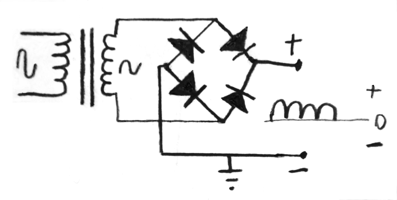
| This circuit uses a "bridge" of four diodes to generate pulses for both positive and waveform, meaning there is a 20 millisecond gap between the peaks on a 50 Hz system, and 16.667 ms in a 60 Hz one. Again the hum frequency is 100 or 120 Hz. I have left the capacitor off this one, so the waveform shown is generated. |
In many cases a supply will include a voltage regulator of some kind. This can be a three terminal regulator, such as the 7800 family, or a design using a zener or similar reference and power transistors. Regulators tend to reduce hum passed to the load. IC regulators may be distributed within a device. Small zener regulators may aso be used for a single transistor amplifer state between a demodulator and the audio power amplifier.
The alternative is the switch-mode power supply (SMPS). These operate at high frequency, from around 25 kHz and up, as if the oscillator runs at an audio frequency, the Audible whine will be very annoying. If a power supply is badly designed there will be a harmonic at every 25 kHz across the MF and HF bands in the radio it supplies. The Jaycar / Powertech MP3079 is definitely one to AVOID!
The electrical arrangement of components in a circuit is drawn out in a "schematic diagram". You should remember that this does not dictate the physical placement of components, as we typically want the indicators, displays, and switches on the front; connectors on the front, side, or rear, depending on their function; and components needing heat-sinking where we wish to place heatsinks.
Sighted candidates are required to identify component on the diagram below.

This appears to be a varactor tuned oscillator, based on a FET, with the bipolar transistor acting as an output driver, connected via a transformer. Adjusting the variable resistor adjusts the frequency. Older VHS machines with channels set up by adjusting a bank of multi-turn trimpots used his concept.
The un-numbered resistors connected to the base of the NPN transistor biases the transistor input.
The capacitor above the transformer is likely to "decouple" or "bypass" RF current from section of the circuit, to help prevent it from travelling along the power wire to other sections of the equipment. A benefit of the zener based voltage regulator is that noise or hum on the power supply is attenuated. The variabe resistor may require 10, 15, or 20 turns using a small screwdriver to travel the track, allowing the voltage, and thus the frequency, to be set with better precision; or it may be a user operated one, with a vernier reduction drive, to more easily tune in stations.
These are actual questions from the General exam pool.
G7A01
What useful feature does a power supply bleeder resistor provide?
A. It acts as a fuse for excess voltage
B. It ensures that the filter capacitors are discharged when power is removed
C. It removes shock hazards from the induction coils
D. It eliminates ground loop current
Especially in power supply circuits which generate a dangerous DC voltage it is common to place a high value resistor across the filter capacitor(s) to discharge them when the power is removed. This reduces the chance of someone who opens the equipment getting a dangerous shock, answer B.
G7A02
Which of the following components are used in a power supply filter network?
A. Diodes
B. Transformers and transducers
C. Quartz crystals
D. Capacitors and inductors
Some power supplies use only capacitors after the rectifier. Others use (typically) iron-cored inductors as well, forming a "filter network". Answer D.
G7A03
What is the peak-inverse-voltage across the rectifiers in a full-wave bridge power supply?
A. One-quarter the normal output voltage of the power supply
B. Half the normal output voltage of the power supply
C. Double the normal peak output voltage of the power supply
D. Equal to the normal peak output voltage of the power supply
There is only the peak voltage of the power supply across the diode in reverse, answer D.
G7A04
What is an advantage of a half-wave rectifier in a power supply?
A. Only one diode is required
B. The ripple frequency is twice that of a full-wave rectifier
C. More current can be drawn from the half-wave rectifier
D. The output voltage is two times the peak output voltage of the transformer
This require only a single diode, saving money, labour, and perhaps space, answer B.
G7A05
What portion of the AC cycle is converted to DC by a half-wave rectifier?
A. 90 degrees
B. 180 degrees
C. 270 degrees
D. 360 degrees
This is very nearly 180 degrees, answer B.
G7A06
What portion of the AC cycle is converted to DC by a full-wave rectifier?
A. 90 degrees
B. 180 degrees
C. 270 degrees
D. 360 degrees
Both the two diode full-wave arrangement using a CT transformer, and the bridge rectifier convert very nearly the 360 degrees of the waveform to DC, answer D.
G7A07
What is the output waveform of an unfiltered full-wave rectifier connected to a resistive load?
A. A series of DC pulses at twice the frequency of the AC input
B. A series of DC pulses at the same frequency as the AC input
C. A sine wave at half the frequency of the AC input
D. A steady DC voltage
Both the positive and negative half-waves become positive half-waves. These pulses thus occur at twice the AC frequency, answer A.
G7A08
Which of the following is an advantage of a switchmode power supply as compared to a linear power supply?
A. Faster switching time makes higher output voltage possible
B. Fewer circuit components are required
C. High frequency operation allows the use of smaller components
D. All of these choices are correct
Switchmode supplies involve converting the AC mains to high voltage DC, then rapidly switching this to feed a small, usually ferrite, transformer. The high frequency often means smaller filter capacitors can be used, answer C.
This often also means they are much lighter.
G7A09
Which symbol in figure G7-1 represents a field effect transistor?
A. Symbol 2
B. Symbol 5
C. Symbol 1
D. Symbol 4
The right angle connections to the bar indicates a FET, as in symbol 1, answer C.
G7A10
Which symbol in figure G7-1 represents a Zener diode?
A. Symbol 4
B. Symbol 1
C. Symbol 11
D. Symbol 5
The 45 degree wings on the cathode indicates a special kind of diode, the zener, Symbol 5, answer D.
G7A11
Which symbol in figure G7-1 represents an NPN junction transistor?
A. Symbol
B. Symbol 2
C. Symbol 7
D. Symbol 11
Bipolar transistors are indicated by the angled connections, and the arrow on an NPN transistor is "Not Pointing iN", answer B.
MP>The PN junction from base to emitter, the last two letters, is needed for the voltage, positive with respect to ground, to drive a base to emitter current to enable the collector to emitter current.G7A12
Which symbol in Figure G7-1 represents a solid core transformer?
A. Symbol 4
B. Symbol 7
C. Symbol 6
D. Symbol 1
The lines indicating the core. This may be an iron powder toroid, given this likely operates at a radio frequency, answer C.
A version without lines indicate it is wound on a small plastic or lacquered paper tube.
G7A13
Which symbol in Figure G7-1 represents a tapped inductor?
A. Symbol 7
B. Symbol 11
C. Symbol 6
D. Symbol 1
This is the component with the appearance of a coil, with a tap, symbol 7, and answer A.
On to: Circuits 2 - Digital & RF Circuits
You can find links to lots more on the Learning Material page.
Written by Julian Sortland, VK2YJS & AG6LE, March 2022.
Tip Jar: a Jefferson (US$2), A$3 or other amount / currency. Thanks!