Home - About AR - Learning Material - Exams - Clubs - Posters
Filters pass some frequencies, and attenuate others. The layout is often similar to attenuators.
Given capacitors pass high frequencies and impede low ones; and inductors pass low frequencies, and impede high ones; it is possible to use them in filters for audio and radio frequencies. They can also match the output impedance of valve / tube amplifiers to a 50 ohm or similar feedline.
At RF capacitors and inductors are used in the majority of cases, as a combination of both reactive components provides a steeper roll-off than say RC. At audio resistors and capacitors may be used, although inductors can be used too, with these being large, say wound on an 8 cm cardboard former in the case of passive crossovers in loudspeakers.Fairly simple filters are the low pass and the high pass filters. Bandpass filters pass a range of frequencies, and band-stop block a certain range. A notch-filter is a narrow (high-Q) band-stop filter.
While many are named for their inventor, simple ones are named for a letter which they look like, be it L (actually rotated 90 degrees), T, Pi (Π/π), or a combination, Pi-L.
The first filter asked about is a low-pass Pi filter. It first has a capacitor to ground which shunts high frequencies to ground while being mostly ignored by low frequencies. This is repeated at the output. Between the two the inductor passes low frequencies, while reducing high frequencies.
Adding a second inductor between the pi filter and the output creates a Pi-L filter which has greater harmonic suppression.
Pi and Pi-L is commonly used for after the final valve / tube in a transmitter or amplifier to match it to a 50 ohm antenna. Additional components are used to isolate the antenna from the very high voltage DC supply, and to blow the supply fuse if the isolation fails.
It is likely worth noting that the components of the filter interact with the output impedance of the preceding circuit, and loading of the following circuit.
A Chebyshev filter has a sharp cutoff. The examiner also indicates it has a ripple in the passband, without noting that this applies to the "Type I" variant; off the paper the Type II version moves the ripple into the stopband. The flatter passband in the second case can be beneficial.
The elliptical filter has an extremely sharp cutoff, but one or more notches in the stop band. Not mentioned, there are also lumps and bumps in the passband before the cutoff is reached.
You can read the Wikipedia articles which include graphs showing the responses, or other materials on these filters. However, rather than circuit diagrams they have a lot of maths.
Off this section, to make the filters above, the inductors and capacitors used at audio to VHF are specific fixed or variable components. At UHF and above they can also be patterns of PCB track or micro-strip. They can also be features inside waveguide at microwave frequencies. There are some components which integrate the parts of a low pass Pi filter, although those tend to be a designed to pass DC and maybe audio, but block RF, rather than having a precise cut off.
DSP is discussed on other pages, but it is important to note that it is used at audio or IF, for low-level signals. Some software defined radio systems may sample HF radio frequencies directly, but this is low level, and it is important to note that they are NOT used for things like duplexers.
I am not aware of audio DSP being placed in an FM repeater's audio chain, but it may be useful to clean up noisy signals - certainly a worthwhile experiment. It may introduce a short delay, although digital repeaters have this too. Even an FM repeater with a RaspberryPi in the audio chain has a small delay, just enough to be confusing if you can hear the repeater's output.
Crystal lattice filters are for low-level RF signals, and are made using a number of quartz crystals in series, typically with a capacitor to ground between each one. Many operate at 10.7 MHz as IF filters in receivers, with 9 MHz also used. While it features in a distractor, high Q is a very important aspect of these filters, but "lattice shaped" is wrong. Lattice instead refers to the pattern in a schematic diagram containing from 3 to 8 crystals, plus capacitors, with "ladder filter" also used. These can be discreet crystals on a PCB, or as small module, including as a 3-pin version of the HC-49 crystal package. The passband typically various from a few hundred Hertz for CW to around 2.7 kHz for SSB to 6 kHz for AM. Filters for a 455 kHz IF are also common.
Collins mechanical filters, typically sold via Inrad which mounts them on small carrier PCBs, are generally considered superior. Unfortunately Collins has discontinued them, with only old stock available. Yaesu also had boards with these mounted for the FT-857D and similar radios. The less costly option is the ceramic filter.
By the way, there is a problem with the three small black plastic housed TOKO 455 kHz filters soldered to the board on the 857 / 897 failing over time. Murata replacements should be used if your radio has problems. See: Replacing Yaesu FT857 IF filters by DH1TW
The cavity filter is used as a duplexer in repeaters, to prevent signals from the transmitter desensitising the receiver, or causing the repeater from locking on. The examiner mentions 2 metres, and in this case they are around 50 cm high, and perhaps just under 20 cm in diameter. One or two coax connectors are fitted to the top, and the top of an invar rod protrudes from the top. The length of this can be adjusted to tune the cavity. The connectors at the top may be fitted with T-adaptors to allow the cavities to be chained together, or they may have input and output terminals. RG-142, RG-223, RG-400, or the thicker RG-214 are likely good choices for connecting them, as they have two braids; lengths may be cut to quarter (or 3/4) wavelength of the frequency of the pass frequency, and half wavelength of the reject one. It is typical to have six, mounted on the floor, wall, or a rack; although four may be used. Additional filters may be added ahead of the receiver, to filter out other two-way system signals, pagers (if still a problem), or broadcast stations. To set them up a spectrum analyser with tracking oscillator; or a VNA, is needed. Transporting them can affect their tune, so they often need to be adjusted when placed in portable repeaters for emergency communications or exercises. For 70 cm and 23 cm they are small enough to sit on a tray in a 19 inch rack, and are typically under 1 unit (44 mm) high. This is a 23 cm Cavity costing around €400. For 6 metres they can be around 2 metres tall if they are from a 10 kW Channel 0 TV transmitter in Australia, or 1.3 metres if for communications power levels.
Off this section, analogue TV stations used separate vision and audio transmitters coupled into the antenna system, with cavities to prevent power going into the other transmitter. The audio is typically 4.5 to 6.5 MHz above the video carrier.
Note that the transmit side operates at between a few watts, and in the US, 1500 watts, although 25 to 100 is most usual. They clearly need high Q, and steep cut-off, given you need to isolate a +20 dBm signal from a -128 dBm one just 600 kHz, or 0.4% apart. With 70 cm having splits between 1.6 and 7 MHz, this is 0.365% to 1.6%. When Australian UHF CB at 477 MHz was established in 1977, the then tory government decided to make repeaters difficult, if not a technically unfeasible legal fiction, with just a 750 kHz "split", or 0.157%. Thus while used commercial grade radios to add a CB repeater to the local communications site may have a trivial cost, as would a RaspberryPi or similar control system, a duplexer costs thousands of dollars, very much more than a used one from a commercial site with a wider split.
A helical filter is used at VHF and UHF. They consist of a coils of stiff wire, each terminated at one end only, fitted within a metal shield. They are quite small, and can fit within a radio. It is worth looking at the image on Wikipedia: Helical resonator to understand what they look like.
A filter might have 3 kHz bandwidth at 3 dB below the centre pass frequency. How well it rejects a strong signal a few more kHz away is down to the steepness of the filter edges. One way to assess this is the shape factor. If the bandwidth is 6 kHz at 30 dB down, then the shape factor at 30/3 dB is 2:1. For the examiner this is a measure of a filter's ability to reject signals in adjacent channels.
There are several options for building a power supply to supply amateur equipment, including transceivers and accessories, typically from the mains supply.
The first is termed a linear supply, consisting of a heavy iron lamination and copper transformer, a diode bridge, and filter capacitor(s). If the circuit supplied is happy to run from a range of voltages, no regulation is needed.
Copper in the transformer is fairly expensive, so this is part of the cost of the power supply, and its mass, along with the iron of the laminations. High value, low voltage capacitors are large and costly, as are the heatsinks which may be needed in the linear regulator.
If regulation is needed, and the load is only an amp, or several amps, the simplest option is a three terminal regulator, such as the 78xx series. In addition to the TO-220 lower current versions (around 1 to 2 amps), there are also higher current TO-3 versions (5 or 10 amps). The other option is to use a Zener or other voltage reference and a series pass transistor. For larger supplies chunky TO-3P or TO-218, and similar packages; or several in parallel, would be ideal. The exam terms these linear regulators. There are also TO-92 versions coded 78Lxx, rated at 100 mA.
It is also possible to build a regulator using an external pass transistor, with a 78xx or similar regulator as the reference. It is also possible to raise the ground pin above ground to increase the output voltage. Search for the datasheet for a 7805 and read the application notes.
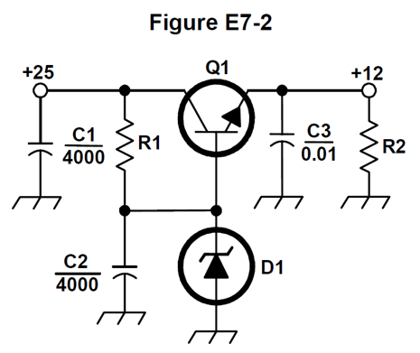
Below is a linear supply's regulator section, although it could also reduce a truck battery's 24 volts to 12 for a car accessory, including a 12 volt CB. Note that if just 1 amp is used by the load, with 13 volts (25 volts - 12 volts), then 13 watts is dissipated in the pass transistor, meaning heatsinking is required. For much more of a load a fan may be needed.
The alternative is a switching power supply. In these the mains supply is rectified, and filtered by electrolytic capacitors typically rated at 400 volts. After this an oscillator drives one or more high voltage transistors, switching current into a physically small transformer, in some cases with a a ferrite core. After this, diodes with a fast response rectify the output. A feedback system typically uses an optocoupler to signal if the voltage is high or low, so that the duty cycle can be adjusted to maintain the desired output voltage over a range of loads.
The DC voltage is 1.4142 times the mains voltage, less the diode drop. Well designed supplies often use 400 volt capacitors, as they are designed to accept between maybe 100 volts and 240 volts. Some may use 350 volts but that means a mains supply floating to 250 volts or more will cause the rating to be exceeded. Professional supplies have a 450 volt capacitor, as this allows an input voltage of 305 volts AC, which is 10% above the nominal value of the industrial 277 volt supply.
Electrolytic capacitors (electros) are also termed aluminium electrolytic, or aluminium.
A shunt regulator loads the unregulated supply down to the desired voltage.
While the Technician paper included a simple supply, shunt regulated by a Zener diode, such arrangements are normally used within a device such as a transceiver, to supply specific low current stages with clean, regulated power. That said, some dodgy cordless 'phones shunt the unregulated supply, meaning that if you replace the supply with a battery based UPS circuit, the regulator will overheat.
All high power supplies require heatsinks on the power transistors or ICs, and some include cooling fans, as do some large amplifiers. The energy lost as heat is however larger in linear units.
There are also oddball arrangements, such as ferro-resonant supplies.
Unless you are closely monitoring the battery voltage, say during a field day operation, you must use a charge controller if you have a station powered by a battery charged via a solar panel. This prevents the battery being damaged by over-charging. The complexity of these varies, but MPPT is the best option.
These are the actual questions from the Extra licence exam pool, as published by the NCVEC.
E7C01
How are the capacitors and inductors of a low-pass filter Pi-network arranged between the network's input and output?
A. Two inductors are in series between the input and output, and a capacitor is connected between the two inductors and ground
B. Two capacitors are in series between the input and output, and an inductor is connected between the two capacitors and ground
C. An inductor is connected between the input and ground, another inductor is connected between the output and ground, and a capacitor is connected between the input and output
D. A capacitor is connected between the input and ground, another capacitor is connected between the output and ground, and an inductor is connected between input and output
A low pass filter uses capacitors to shunt high frequencies to ground, and a series inductor to block or reduce these; while low frequencies are not shunted greatly, nor reduced significantly by the inductor. The Pi configuration has elements (caps) to ground at the input and output, and a single series element (inductor), in the shape of the letter pi, π, answer D.
E7C02
What is the frequency response of a T-network with series capacitors and a shunt inductor?
A. Low-pass
B. High-pass
C. Band-pass
D. Notch
The series capacitors pass high frequencies, and block low ones, while the inductor shunts low frequencies to ground, while doing little to high frequency signals, so it is a high-pass filter, answer B.
E7C03
What is the purpose of adding an inductor to a Pi-network to create a Pi-L-network?
A. Greater harmonic suppression
B. Higher efficiency
C. To eliminate one capacitor
D. Greater transformation range
A filter with additional elements has greater harmonic suppression, answer A.
E7C04
How does an impedance-matching circuit transform a complex impedance to a resistive impedance?
A. It introduces negative resistance to cancel the resistive part of impedance
B. It introduces transconductance to cancel the reactive part of impedance
C. It cancels the reactive part of the impedance and changes the resistive part to a desired value
D. Reactive currents are dissipated in matched resistances
The reactive elements cancel the reactive part of the impedance, and changes the resistive part to a desired value, answer C.
E7C05
Which filter type has ripple in the passband and a sharp cutoff?
A. A Butterworth filter
B. An active LC filter
C. A passive op-amp filter
D. A Chebyshev filter
This is the Chebyshev filter, answer D.
E7C06
What are the characteristics of an elliptical filter?
A. Gradual passband rolloff with minimal stop-band ripple
B. Extremely flat response over its pass band with gradually rounded stop band corners
C. Extremely sharp cutoff with one or more notches in the stop band
D. Gradual passband rolloff with extreme stop band ripple
The cutoff is extremely sharp, with one or more notches in the stop band C.
Sharp cutoff often has the cost of ripple or other irregular response on one or both sides of the cutoff.
E7C07
Which describes a Pi-L network?
A. A Phase Inverter Load network
B. A Pi-network with an additional output series inductor
C. A network with only three discrete parts
D. A matching network in which all components are isolated from ground
This is a Pi-network with an extra series inductor on the output, answer B.
It can help improve the match to the 50 ohm antenna terminal.
E7C08
Which of the following is most frequently used as a band-pass or notch filter in VHF and UHF transceivers?
A. A Sallen-Key filter
B. A helical filter
C. A swinging choke filter
D. A finite impulse response filter
This is the helical filter, answer B.
E7C09
What is a crystal lattice filter?
A. A power supply filter made with interlaced quartz crystals
B. An audio filter made with four quartz crystals that resonate at 1 kHz intervals
C. A filter using lattice-shaped quartz crystals for high-Q performance
D. A filter for low-level signals made using quartz crystals
Crystal lattice filters are typically used in the IF stage, or perhaps in some filters used in SSB generation, which is done at low levels, answer D.
E7C10
Which of the following filters would be the best choice for use in a 2-meter repeater duplexer?
A. A crystal filter
B. A cavity filter
C. A DSP filter
D. An L-C filter
Cavity filters are the only sane choice for duplexers at VHF frequencies, answer B.
E7C11
Which of the following describes a receiving filter's ability to reject signals occupying an adjacent channel?
A. Passband ripple
B. Phase response
C. Shape factor
D. Noise factor
This is shape factor, answer C.
A good shape factor means that adjacent channels are rejected.
E7D01
How does a linear electronic voltage regulator work?
A. It has a ramp voltage as its output
B. It eliminates the need for a pass transistor
C. The control element duty cycle is proportional to the line or load conditions
D. The conduction of a control element is varied to maintain a constant output voltage
The conduction of the control element (internal series pass transistor) is controlled so the output voltage is constant, answer D.
E7D02
How does a switchmode voltage regulator work?
A. By alternating the output between positive and negative voltages
B. By varying the duty cycle of pulses input to a filter
C. By varying the conductivity of a pass element
D. By switching between two Zener diode reference voltages
The duty cycle at which the transistor or FET is driven is varied to produce the correct voltage from the filter output, answer B.
E7D03
What device is used as a stable voltage reference?
A. A Zener diode
B. A digital-to-analog converter
C. An SCR
D. An analog-to-digital converter
A Zener diode is used, answer A.
There are also a range of alternate voltage reference diodes. and 2 or 3 pin ICs. They are used as a reference, not to power other devices.
E7D04
Which of the following describes a three-terminal voltage regulator?
A. A series current source
B. A series regulator
C. A shunt regulator
D. A shunt current source
The 78xx (and LM340) IC regulators are termed series regulators. The output current passes through the internal pass transistor, answer B.
E7D05
Which of the following types of linear voltage regulator places a constant load on the unregulated voltage source?
A. A constant current source
B. A series regulator
C. A shunt current source
D. A shunt regulator
They are trying to describe is a shunt regulator, answer D, where an extra load reduces the output voltage to the desired level. A Zener (possibly a stud-mount one) is a typical load element.
E7D06
What is the purpose of Q1 in the circuit shown in Figure E7-2?
A. It provides negative feedback to improve regulation
B. It provides a constant load for the voltage source
C. It controls the current to keep the output voltage constant
D. It provides regulation by switching or "chopping" the input DC voltage
This increases the current supply capability of the circuit, answer C.
E7D07
What is the purpose of C2 in the circuit shown in Figure E7-2?
A. It bypasses rectifier output ripple around D1
B. It is a brute force filter for the output
C. To self-resonate at the hum frequency
D. To provide fixed DC bias for Q1
It bypasses (filters) ripple or hum coming from the rectifier to D1, answer A.
This means that even if there is hum remaining on C1 and the collector of Q1 a clean reference voltage will be present at the base of the transistor, and hopefully the output has any hum suppressed.
E7D08
What type of circuit is shown in Figure E7-2?
A. Switching voltage regulator
B. Common emitter amplifier
C. Linear voltage regulator
D. Common base amplifier
This is a linear voltage regulator, made from discrete components, answer C.
E7D09
How is battery operating time calculated?
A. Average current divided by capacity in amp-hours
B. Average current divided by internal resistance
C. Capacity in amp-hours divided by average current
D. Internal resistance divided by average current
Divide the capacity by the average current, answer C.
Say you have a 10 AH battery and a radio which draws the 2 amps then the the life will be 10 / 2 = 5 hours.
E7D10
Why is a switching type power supply less expensive and lighter than an equivalent linear power supply?
A. The inverter design does not require an output filter circuit
B. The control circuitry uses less current, therefore smaller heat sinks are required
C. The high frequency inverter design uses much smaller transformers and filter components for an equivalent power output
D. It recovers power from the unused portion of the AC cycle, thus using fewer components
The mains voltage is rectified to high voltage DC, and this is then fed into a small transformer through chopping transistors, a circuit which can be termed an inverter. As the frequency is high, the transformer and filter capacitors can also be smaller. The smallness of these parts can reduce cost and weight, answer C.
Using less costly copper helps reduce the cost, and less steel the mass.
E7D11
What is the purpose of an inverter connected to a solar panel output?
A. Reduce AC ripple on the output
B. Maintain voltage with varying illumination levels
C. Prevent discharge when panel is not illuminated
D. Convert the panel's output from DC to AC
This is discussing grid connected home solar panels or similar systems. Either the panels are strung together in series feeding a single inverter with high voltage DC, or occasionally systems have a small inverter on each panel paralleled together, operating in sync. Answer D.
You can also connect low voltage panels to a 12 or 24 volt battery, and feed an inverter to get mains voltage AC.
E7D12
What is the dropout voltage of an analog voltage regulator?
A. Minimum input voltage for rated power dissipation
B. Maximum output voltage drop when the input voltage is varied over its specified range
C. Minimum input-to-output voltage required to maintain regulation
D. Maximum that the output voltage may decrease at rated load
If we have a basic 7805, we need to have at least 8 volts on the input, and we call this required overhead, or minimum input to output difference, the drop-out voltage, in this case 3 volts. Answer C.
There are also specialist LDO (low drop-out) regulators, which can work with an input something like 40 milivolts above the output rail. They often have a lower maximum input voltage than a standard device, say 12 volts instead of 35 volts for a 5 volt output unit.
E7D13
Which of the following calculates power dissipated by a series linear voltage regulator?
A. Input voltage multiplied by input current
B. Input voltage divided by output current
C. Voltage difference from input to output multiplied by output current
D. Output voltage multiplied by output current
Take the above example, 8-5=3 volts, and if we were pulling the full amp, the dissipation would be 3 watts. If we were dropping from 28 to 12 volts, at 0.75 amps, we have P = (28-12) x 0.75 = 16 x 0.75 = 12 watts, needing a fairly decent heat-sink. P = (VIN-VOUT) × IOUT, answer C.
E7D14
What is the purpose of connecting equal-value resistors across power supply filter capacitors connected in series?
A. Equalize the voltage across each capacitor
B. Discharge the capacitors when voltage is removed
C. Provide a minimum load on the supply
D. All these choices are correct
These equalise the voltage across the capacitors. Move importantly, it helps prevent electric shock if it is a high voltage supply, and someone goes "fingerpoken" in the supply (as long as it has been turned for a few moments). They also provide a minimum load, to prevent the voltage floating too high. It is this all of these, answer D.
E7D15
What is the purpose of a step-start circuit in a high voltage power supply?
A. To provide a dual-voltage output for reduced power applications
B. To compensate for variations of the incoming line voltage
C. To prevent arcing across the input power switch or relay contacts
D. To allow the filter capacitors to charge gradually
Initially starting the supply via resistors allows the filter capacitors to charge more gently, answer D.
It also limits the in-rush current caused by transformer magnetising current, which can be evidenced by a "boing" sound , especially when it resonates through a sheet metal case.
On to: Practical Circuits 3 - Modulation & DSP
You can find links to lots more on the Learning Material page.
Written by Julian Sortland, VK2YJS & AG6LE, November 2025.
Tip Jar: a Jefferson (US$2), A$3 or other amount / currency. Thanks!
You can also buy me a non-coffee beverage: ko-fi.com/ag6le