Home - About AR - Learning Material - Exams - Clubs - Posters
Amateur Radio Info & Exams - Practical Circuits 4 - Op-amps, Filters & Oscillators
Oscillators
While there are a great many oscillator formats, three which are important in Amateur Radio are Colpitts, Hartley, and Pierce. Each dates from the 1910s or 1920s, so clearly predates transistors. Each format can however be implemented using a valve or tube, a BJT, or a range of FETs as the active element. Some can also be implemented using an Op-Amp.
The Colpitts and Hartley oscillators are LC (inductor and capacitor based) circuits.
The Hartley uses a tapped inductor (measured in Henries) for feedback; while the Colpitts using a Capacitive divider.
The Pierce, a crystal based oscillator can also be made using an inverter logic gate, and as such is widely used in digital electronics, including computers. Mr Pierce used a piece, or sliver, of quartz crystal. I suppose the inverter based Pierce is fairly easy to understand: At start up, we can assume that the capacitor on the input will be discharged, pulling the input low, and thus driving the output high. This in turn drives the input high, and output low, and so on, at a frequency determined by the crystal.
Use in Amateur and two-way Radio
Thus, in days of old, a typical Ham's transmitter used a single crystal, providing a single transmitter frequency, so if Fred and Bill talked, Bill would tune his receiver to Fred's frequency, and Fred would set his to Bill's crystal frequency. A second crystal for a club frequency would be sheer luxury. Eventually, and presumably using Colpitts or Hartley type designs, Variable Frequency Oscillators (VFOs) were applied to the transmitters.
Around the 1970s, mobile business and government service radios (PMR), as well as CBs, and for a longer period to "shoe-phone" sized 27 MHz CB hand-helds used one, or a pair of crystals for each channel, so a user may only have a handful of channels in their radio. This contributed to the larger size of such equipment.
In many cases there is a small capacitor either directly in parallel with the crystal, as alluded to in the exam, or from each end to ground. These provide a load to the crystal, and are selected according to the specification of the crystal maker. Some radios may have a small trimmer capacitor in this position, allowing a slight tweak of the frequency.
PLL
However, we wish to generate a range of frequencies to tune a receiver with a digital display, or to set the 40 or 80 discreet channels in a CB, without requiring a crystal, or a pair of crystals, for each channel; and likewise on a 2 metre transceiver. This is achieved using a phase-locked loop, or PLL. These consist of electronic servo loop* consisting of a phase detector, a low-pass filter, a voltage-controlled oscillator, and a stable reference oscillator.
* A "Servo" or Servomechanism is a system in which a circuit responds to ensure a commanded state is maintained. This could be an air-conditioner which heats when it is cold, and automatically cools if it becomes too warm (but with a comfort range, so the device is not constantly switching between the two modes of operation). Radio control folks will recognise the term, for the small motorised devices which also contain a potentiometer so that a steering position is maintained, despite a bumpy track.
PLL circuits are typically under the control of some sort of digital logic system or processor, with the later able to provide memories, automatic scanning, etc.
DDS
Direct Digital Synthesis is a way to generate a an RF or IF frequency using a processor, look-up table, and D-to-A converter. They can be used to replace frequency control sections in ex-PMR radios placed into Amateur band service. (Note that you can't significantly modify type-approved radios if you are placing them on non-Amateur frequencies used by volunteer groups.)
Operational Amplifiers
Bit of an odd name for an amplifier, why not just "pre-amp", etc? This is because these were originally designed to perform mathematical operations in analogue computers, and certainly they can be used in various forms of instrumentation.
The IDEAL device has infinite input impedance, infinite gain, infinite bandwidth, but zero output impedance. Realistically, the impedance is very high, gain also very high, but it does fall off with frequency. Output impedance is low.
As an amplifier with infinite, or even very high gain is often impractical (it would snap to the rails at a nanovolt above or below zero volts input), we place a feedback loop around device, to set the gain. Normally, we just use resistors, and this gives the a gain which is constant over a wide frequency range, until we reach the physical limits of the device.
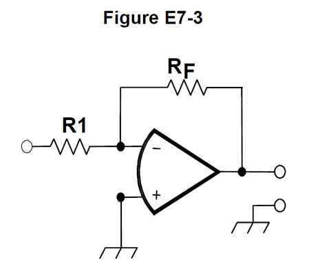 | The "closed loop" gain is determined by the values of the resistors, R1 and RF, thus: G = -R1/RF. As the signal is fed into the negative (inverting) input, the output will be inverted. Several questions ask for the absolute value, or magnitude, of the gain. If RF is 10,000, and R1 is 400, then the gain is |-10000/400| = |-25| = 25, the bars indicating absolute value. Normally you just ignore the signs and do 10000/400 = 100/4.
The nice things about op-amps is that, say we needed to boost an audio signal from a church mixing desk into a recording device, especially if we were using unbalanced (RCA or some 6.5 mm plug configurations), we just need a couple of DC isolation capacitors, a battery or small power supply, decoupling capacitors on the supply pins, and we have the booster we need; duplicate, using a dual op-amp IC, for stereo; all in an "Altoids" mints container. |
Off the exam, each type of Op-Amp has a "Gain–bandwidth product", the point at which the open-loop gain drops to 1. As this line is linear, we can calculate the maximum voltage gain at a certain frequency. A typical figure is 1 MHz, and if we want to amplify a 40 kHz signal from an ultrasonic transducer, we find the gain is limited to 25. If we wanted more gain, we would either need to select a unit with a higher figure, or use two stages of gain. Modern surface mount devices are pushing this GBWP figure out to hundreds of MHz.
Active filters
While there are various implementations, if we place a reactive device in the feedback loop, we can use the device as a filter, especially at signal levels at audio frequencies.
Now going beyond the paper, inductors for audio frequencies tend to be large, heavy, and costly, but place a capacitor in the negative feedback loop, and we get a greater feedback for high frequencies, meaning less gain than at low frequencies, so this "gyrator" circuit emulates an inductor, and these are useful in filters, including graphic equalizers. Using capacitors and resistors either within the loop, or outside it, or both, enables you to build an "RIAA" equalised pre-amplifier, to connect a phonograph (record) player to a line-in connection on an amplifier or PC.
Relevant Questions
These are the actual questions from the Extra licence exam pool, as published by the NCVEC.
E7G01
What is the typical output impedance of an integrated circuit op-amp?
A. Very low
B. Very high
C. 100 ohms
D. 1000 ohms
The output impedance is very low, answer A.
E7G02
What is ringing in a filter?
A. An echo caused by a long time delay
B. A reduction in high frequency response
C. Partial cancellation of the signal over a range of frequencies
D. Undesired oscillations added to the desired signal
If the filter has a very narrow bandwidth (high Q), then when a signal which falls into its bandwidth, especially one keyed on and off like a Morse signal, there is a tendency for "ringing", just as a bell or tuning fork resonates when struck, or one tuning fork will begin to vibrate if another which is ibrating is placed near it. These oscillations are, however, undesirable, answer D.
E7G03
What is the typical input impedance of an integrated circuit op-amp?
A. 100 ohms
B. 1000 ohms
C. Very low
D. Very high
In most cases we want the input to test equipment or audio amplifiers to be high impedance, and this is the case with op-amps, answer D.
E7G04
What is meant by the "op-amp input offset voltage"?
A. The output voltage of the op-amp minus its input voltage
B. The difference between the output voltage of the op-amp and the input voltage required in the immediately following stage
C. The differential input voltage needed to bring the open loop output voltage to zero
D. The potential between the amplifier input terminals of the op-amp in an open loop condition
The differential input voltage needed to bring the open loop output voltage to zero, answer C.
While specialist Op-amps can have an offset under 1 μV, typical ranges are 10 μV to 50 mV.
E7G05
How can unwanted ringing and audio instability be prevented in a multi-section op-amp RC audio filter circuit?
A. Restrict both gain and Q
B. Restrict gain but increase Q
C. Restrict Q but increase gain
D. Increase both gain and Q
Reducing the gain and the Q reduces the tendency to ring, or become unstable, answer A.
E7G06
What is the gain-bandwidth of an operational amplifier?
A. The maximum frequency for a filter circuit using that type of amplifier
B. The frequency at which the open-loop gain of the amplifier equals one
C. The gain of the amplifier at a filter's cutoff frequency
D. The frequency at which the amplifier's offset voltage is zero
The frequency at which the open-loop gain is reduced one, answer B.
E7G07
What magnitude of voltage gain can be expected from the circuit in Figure E7-3 when R1 is 10 ohms and RF is 470 ohms?
A. 0.21
B. 94
C. 47
D. 24
The absolute value of the voltage gain is 470 / 10 = 47, answer C.
E7G08
How does the gain of an ideal operational amplifier vary with frequency?
A. It increases linearly with increasing frequency
B. It decreases linearly with increasing frequency
C. It decreases logarithmically with increasing frequency
D. It does not vary with frequency
It is important to note the word "ideal", so the gain is very high, or infinite, as is the frequency response. Thus, it does not vary, answer D.
E7G09
What will be the output voltage of the circuit shown in Figure E7-3 if R1 is 1000 ohms, RF is 10,000 ohms, and 0.23 volts DC is applied to the input?
A. 0.23 volts
B. 2.3 volts
C. -0.23 volts
D. -2.3 volts
10,000 / 1000 is 10, but note we are using the inverting input, and get so we need to multiply 0.23 by -10, and get 2.3 volts, answer D.
E7G10
What absolute voltage gain can be expected from the circuit in Figure E7-3 when R1 is 1800 ohms and RF is 68 kilohms?
A. 1
B. 0.03
C. 38
D. 76
Hmmm, 68000 / 1800 is 680 / 18, or halve it to 340/9, and only 38 is in the ball-park, answer C.
Bash the keys, and get 37.77777777778.
E7G11
What absolute voltage gain can be expected from the circuit in Figure E7-3 when R1 is 3300 ohms and RF is 47 kilohms?
A. 28
B. 14
C. 7
D. 0.07
Gain = RF / R1 = 47000 / 3300 = 470 / 33, which has to be more than 10, but less than 20, so answer B, but better bang it into a calculator, and get 14.2424. You will note that the voltage is fed into the inverting (-) input, so the value would be negative, but you will also see that they are asking for the Absolute value.
E7G12
What is an operational amplifier?
A. A high-gain, direct-coupled differential amplifier with very high input impedance and very low output impedance
B. A digital audio amplifier whose characteristics are determined by components external to the amplifier
C. An amplifier used to increase the average output of frequency modulated amateur signals to the legal limit
D. A RF amplifier used in the UHF and microwave regions
An op-amp is an analogue device which typically operates from DC to high audio or low RF frequencies, and are usually low power devices, with the characteristics in answer A.
The name operational amplifier comes from these devices being designed for performing mathematical functions in ANALOGUE computers.
E7H01
What are three oscillator circuits used in Amateur Radio equipment?
A. Taft, Pierce and negative feedback
B. Pierce, Fenner and Beane
C. Taft, Hartley and Pierce
D. Colpitts, Hartley and Pierce
It is Colpitts, Hartley, and Pierce, answer D.
Taft was the 27th President, from a political dynasty in the early 1900s, not an oscillator inventor; Prof Frank Fenner was an Australian who led the eradication of Smallpox, working at ANU in Canberra; and the Beane name is more associated sports. Or maybe it refers to stockbrokers?
E7H02
What is a microphonic?
A. An IC used for amplifying microphone signals
B. Distortion caused by RF pickup on the microphone cable
C. Changes in oscillator frequency due to mechanical vibration
D. Excess loading of the microphone by an oscillator
If electronics reacts to being knocked or vibrated, then it is said to be "microphonic", answer C.
E7H03
How is positive feedback supplied in a Hartley oscillator?
A. Through a tapped coil
B. Through a capacitive divider
C. Through link coupling
D. Through a neutralizing capacitor
Hartley's design uses a tapped coil, answer A.
As we know, inductors are measured in Henries, or H; H for Hartley!
E7H04
How is positive feedback supplied in a Colpitts oscillator?
A. Through a tapped coil
B. Through link coupling
C. Through a capacitive divider
D. Through a neutralizing capacitor
The Colpitts uses a capacitive divider answer C.
The position of the answer may very on the paper, but Colpitts and Capacitor both start with C.
E7H05
How is positive feedback supplied in a Pierce oscillator?
A. Through a tapped coil
B. Through link coupling
C. Through a neutralizing capacitor
D. Through a quartz crystal
These can be made using a triode, bipolar transistor, various FETs, and most often now, a digital inverter; but all have one thing in common, a crystal, answer D.
The full name for a crystal is a "piezoelectric crystal". P for Piezo and Pierce (might get you a piece of pie in nerdy Trivial Pursuit).
E7H06
Which of the following oscillator circuits are commonly used in VFOs?
A. Pierce and Zener
B. Colpitts and Hartley
C. Armstrong and deForest
D. Negative feedback and balanced feedback
Colpitts and Hartley are two types of oscillator used in VFOs. These use capacitors or inductors which can be variable, rather than a crystal. Answer B.
E7H07
How can an oscillator's microphonic responses be reduced?
A. Use NP0 capacitors
B. Reduce noise on the oscillator's power supply
C. Increase the bias voltage
D. Mechanically isolate the oscillator circuitry from its enclosure
Mechanical isolation of the oscillator is an important step, answer D.
E7H08
Which of the following components can be used to reduce thermal drift in crystal oscillators?
A. NP0 capacitors
B. Toroidal inductors
C. Wirewound resistors
D. Non-inductive resistors
NP0 capacitors (that is a zero, by the way), answer A.
E7H09
What type of frequency synthesizer circuit uses a phase accumulator, lookup table, digital to analog converter, and a low-pass anti-alias filter?
A. A direct digital synthesizer
B. A hybrid synthesizer
C. A phase-locked loop synthesizer
D. A diode-switching matrix synthesizer
Watch out for the phase bit, but read through to the "digital to analog converter" part, and realise this must be direct digital synthesizer, answer A.
E7H10
What information is contained in the lookup table of a direct digital frequency synthesizer (DDS)?
A. The phase relationship between a reference oscillator and the output waveform
B. Amplitude values that represent the desired waveform
C. The phase relationship between a voltage-controlled oscillator and the output waveform
D. Frequently used receiver and transmitter frequencies
Just as a CD, .WAV file, or PCM audio stream on an ISDN telephone contains the values to represent an audio waveform, the look-up table in a DDS contains the values needed to output a sine wave (etc) at a range of RF frequencies, answer B.
E7H11
What are the major spectral impurity components of direct digital synthesizers?
A. Broadband noise
B. Digital conversion noise
C. Spurious signals at discrete frequencies
D. Nyquist limit noise
Spurious signals at discrete frequencies, answer C.
E7H12
Which of the following must be done to insure that a crystal oscillator provides the frequency specified by the crystal manufacturer?
A. Provide the crystal with a specified parallel inductance
B. Provide the crystal with a specified parallel capacitance
C. Bias the crystal at a specified voltage
D. Bias the crystal at a specified current
You will frequently see a small, typically ceramic capacitor in parallel with each crystal, such as in an older commercial / government / PMR radio. These provide a small load to the crystal. 15 pF (picofarads) is a typical value, answer B.
In some cases there are capacitors from each side of the crystal to ground. Note also that there is capacitance in holders, and within the crystal, to its metallic housing, which may or may not be grounded.
E7H13
Which of the following is a technique for providing highly accurate and stable oscillators needed for microwave transmission and reception?
A. Use a GPS signal reference
B. Use a rubidium stabilized reference oscillator
C. Use a temperature-controlled high Q dielectric resonator
D. All of these choices are correct
Each of these can provide a frequency with high accuracy and stability, answer D.
E7H14
What is a phase-locked loop circuit?
A. An electronic servo loop consisting of a ratio detector, reactance modulator, and voltage-controlled oscillator
B. An electronic circuit also known as a monostable multivibrator
C. An electronic servo loop consisting of a phase detector, a low-pass filter, a voltage-controlled oscillator, and a stable reference oscillator
D. An electronic circuit consisting of a precision push-pull amplifier with a differential input
A PLL is used to generate a range of frequencies to tune a receiver with a digital display, or to set the 40 or ~80 descreet channels in a CB, without requiring a crystal, or a pair of crystals for each channel, C.
E7H15
Which of these functions can be performed by a phase-locked loop?
A. Wide-band AF and RF power amplification
B. Comparison of two digital input signals, digital pulse counter
C. Photovoltaic conversion, optical coupling
D. Frequency synthesis, FM demodulation
PLLS are often used for frequency synthesis, such as generating channels in a CB or modern PMR radio. It is also possible to use the difference (or "error") signal, in order to demodulate FM signals. Answer D.
On to: Signals & Emissions 1 - Waveforms & Modulation
You can find links to lots more on the Learning Material page.
Written by Julian Sortland, VK2YJS & AG6LE, June 2022.
Tip Jar: a Jefferson (US$2), A$3 or other amount / currency. Thanks!