Home - About AR - Learning Material - Exams - Clubs - Posters
These are two horizontally polarised antennas which are fairly easy to build, and which have some gain over a dipole.
Loop antennas can be pretty much any shape, although the Delta, or triangle is convenient. Square and rectangular are options; and perhaps at higher frequencies, rings of tubing or rod. Inverted deltas and diamonds would also work.
Named for the Greek character Delta, Δ, this a loop antenna, having 3 equal slides, typically fed in the middle of the base. The wire loop is around one full wavelength, so each side is around 2 metres. If fed at the base the antenna is horizontally polarised, which is the recommended polarisation for SSB, CW and most AM operation on VHF and UHF. It is used standing up, and has some gain broadside to the plane of the antenna, meaning that it may be necessary to rotate it.
I built the 6 metre Delta for the spring VHF-UHF Field Day in Australia. It should work well for ARRL Field Day, other contests, and various "-on-the-air" activations where 6 metres is used.

Tools needed are wire cutter & stripper, a small sharp knife or coax stripper, a small saw, soldering iron, and coax termination tools. Ideally, a drill with bit to suit wire diameter.
I have made a range of 6 metre contacts on this antenna, over 700+ km, and have heard a station well over 1000 km away. I have also made contacts on 2 metres SSB using it.
Materials required are:
I used 3 metres of a Jaycar cable with a pair of power wires and RG-59 coax, which I split apart. Their part number is WB2017.
This wire is 20 AWG, which is around 0.5 mm². 0.75 mm² or similar is fine, or Jaycar WH-2050 10 A mains hook-up wire. Colour doesn't matter, although black tends to be the most UV resistant, and grey may be less visible.
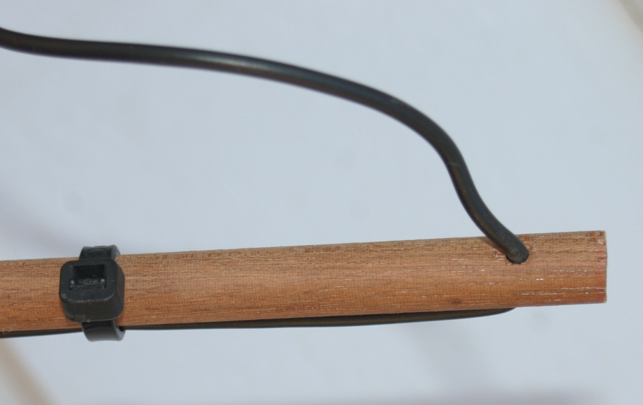
For the base of the triangle I bought a 2.4 metre piece of 9.5 mm dowel (3/8”) and cut it 20mm longer than the base element. I drilled a hole 10 mm from each end to allow the wire to pass through. Experiment on the off-cut for the best diameter for your wire. Mine was 3mm, close to 1/8” or US No 31. If you don't have a drill you could use zip-ties instead. I also filed a shallow notch in the centre, parallel to the holes, to help locate the coax. A chainsaw sharpening file is suitable.
I soldered the ends to the top of the coax, and also to the coax transformer joint discussed below. Soldering at the top is only necessary if you use wire split the power and coax listed above.

I used black cable-ties to secure each wire to the dowel close to each hole, half-way and near the feed-point. Note that each wire makes a lazy half turn around the dowel. If you are installing the antenna, rather than using it on a sunny Field Day, some form of weather protection would be required for the feeder joint, and the dowel should be painted or lacquered to prevent it becoming water-logged and conductive. Many wire cutters or "flush cutters", including Jaycar TH-1890 provide a flush cut to the cable tie end, especially if you tension it as you snip.
The calculator site indicated that the impedance would be 102 ohms, and recommended the use of an antenna tuner. However, it is possible to use a quarter wave length of 75 ohm coaxial cable to transform this impedance to 50 ohms. Its length must take the cable's velocity factor into account. I assumed a Vf of 0.82 so cut the RG-59 to 1.224 metre as the transition to RG-58. At 50.150 MHz this presented an acceptable SWR to my radio without a tuner.
I did however use my LDG YT-100 tuner, which works at 6m, and allowed use the antenna at 52.150 MHz, where Standard licensees often call during contests.
I mounted it by removing the flexible end from a squid pole (through the removable base) and taping and zip-tying a clothes-peg to the top, and hanging the apex of the triangle from this. I stabilised the feed-point area with a little tape each time I put it up. I taped the bottom of the pole to a fence-post or similar convenient item in the field. A STAR-picket is also an option. It was possible to slightly lower and rotate a segment of the pole to change direction. Gaffer / gaffa / duck / duct tape may be useful for this.

I used about 5 metres of RG-58C/U, which uses a multi-strand centre soldered to the bottom of the RG-59. At 50 MHz total feeder loss, including the transformer section should be under 1 dB, and even on a very hot sunny day it will handle well over 100 watts average power.
To determine the wire length in metres use the formula L = 306 / f, where the frequency is in MHz.
The table below, in MHz and metres, includes lengths calculated from KA1FSB's code, now offline. Two sites replicating it are run by ON6WG and IW5EDI.
For the Base number I added 20 mm to allow for the space beyond the holes.
The quarter-wave section of 75 Ω coax must take velocity factor into account. Having 300 on the left of the formula, and dividing by 4 can be short-cut by using 75 here. Lc = 75 / frequency × VF.
If you are unsure, consult the cable manufacturer's data for the VF. Were you to build one for higher power using a RG-11 style cable such as Belden's 9292, you'd use 0.84 as the VF. The 300 volt rating puts the power limit at 1 kW. Their Mil-spec RG-11, such as 9212 has a VF of 0.66, while the 3000 volt rating would not be troubled by 1.5 kilowatts. FSJ1-75 has a has a VF of 0.78, or 78%. Clearly, a wire of several square millimetres should be used at high power.
RG-6 could also be used. The less usual solid PE (such as Belden 8215) is 0.66, while the more standard foam type (such as Belden 9290)is 0.81.
The 75 in the formula is coincidence, and would apply even if another impedance cable was used, for a different match.
I have included lengths for the quarter wave transformer using foam (or “gas injected”) RG-59 with a Vf of 0.82 and solid Polyethylene RG-59/U with a Vf of 0.66. Vf can also be expressed a percentage, such as 82%. While I have given lengths to the millimetre, if you are off a little all that will happen is that the impedance will be a few percent off, and in fact, in theory these numbers should result in a 48 ohm impedance. These variations are unimportant.
Ideally I would have used connectors on the 75 ohm cable as well. One option would be F connectors, especially with RG-6 or RG-11. An adaptor from F to a 50 ohm connector would then be used. TNC, BNC, or similar 75 ohm connectors are option for RG-59, and these match to 50 ohm connectors, even if the match is not ideal.
| Frequency | Wire | Base | Foam | Solid | Use |
|---|---|---|---|---|---|
| 50.000 | 6.126 | 2.062 | 1.230 | 0.990 | CW |
| 50.110 | 6.113 | 2.058 | 1.227 | 0.988 | USB Calling |
| 50.150 | 6.108 | 2.056 | 1.226 | 0.987 | VHF Contest |
| 50.400 | 6.078 | 2.046 | 1.220 | 0.982 | AM |
| 52.150 | 5.874 | 1.978 | 1.179 | 0.949 | Standards |
| 52.525 | 5.832 | 1.964 | 1.171 | 0.942 | FM Calling |
If the coax is run to the top of the mast, and the antenna is fed at the apex (tip) then the polarisation will be mixed, and probably better for communicating with FM stations which are vertical, such as at 52.525 MHz, or repeater frequencies.
Using a horizontal piece at the top reduces the vertical distance between the bottom and the top of the antenna.
Note that I have not yet built this, so this is a little theoretical.
For this you will need:
Tobin bronze appears to be a brass, and is one example of the materials used for brazing. This is a high temperature version of soldering, used for mechanical bonding. The rod is also handy for making quarter-wave antennas for 2 metres and higher frequencies.
The L = 306 / f formula gives us the overall length. Subtract the metre from this for wire length, noting you want a centimetre or two for soldering to the rod. The distance between holes in the dowel will be 2.380, allowing the holes to be 10 mm from each end.
If you can get a longer, ideally slightly heavier, rod, use that, and recalculate the wire length. Ditto of you can get a longer dowel. Either or both will move the lower part of the antenna closer to the top part.
| Frequency | Total | Wire | Side | Foam | Solid | Use |
|---|---|---|---|---|---|---|
| 28.000 | 10.929 | 9.929 | 3.774 | 2.196 | 1.768 | CW |
| 28.300 | 10.813 | 9.813 | 3.716 | 2.173 | 1.749 | SSB |
| 28.450 | 10.756 | 9.756 | 3.688 | 2.162 | 1.740 | WICEN |
| 28.885 | 10.594 | 9.594 | 3.607 | 2.129 | 1.714 | 6m Liaison |
| 29.200 | 10.479 | 9.550 | 3.585 | 2.106 | 1.695 | VK FM Calling |
| 29.600 | 10.338 | 9.338 | 3.479 | 2.078 | 1.672 | DX FM Calling |
You could also use dowel at the top, and even make the antenna rectangular.
If you have large trees, or can get tall utility poles stood up on your land, loop antennas for bands from 160 metres and HF bands are possible. Likewise stranded wire loop antennas are suitable for European bands such as 8 metres, 5 metres, 4 metres; and for 2 metres to maybe 33 cm. Overlapping this, from around 70 cm and beyond brazing rod, thick single-strand wire, or similar products can be used.
You can use L = 306 / f, where f is in MHz; or KA1FSB's code, on the ON6WG or IW5EDI pages.
For FM-broadcast (3 metre band) and TV reception in good areas, you can feed it directly into 75 ohm coax. You could use a 90-odd ohm coax as a transformer, but for reception there is little need. Design the antenna for the lowest frequency in use.
You can find links to training material on the Learning Material page.
These pages have taken a fair bit of work to write, so if you have found this useful, there is a "tip jar" or KoFi links.
Written by Julian Sortland, VK2YJS & AG6LE, March 2026.
Tip Jar: A Jefferson (US$2), A$3, 3 Singapore Dollars or another amount or currency. Thanks!
You can also buy me a non-coffee beverage: ko-fi.com/ag6le
☕🥤