
Above this is a 100kΩ 1% resistor, the red indicating a temperature co-efficient of 50 pm/°C
Uppermost appears to be a small zener diode, in a glass case.
These are mounted on a fibreglass printed curcuit board. You can see the traces through it.
Home - About AR - Learning Material - Exams - Clubs - Posters
The Examination requires candidates whose vision allows them to do so to identify specific component symbols on three sample circuit diagrams or "schematics". Several of the questions below do not refer to the supplied diagrams, so apply to all candidates.
Schematic diagrams show the interconnections of components, but not the physical layout; and are not to scale. While Americans and Europeans use different symbols for some components, and vary in structure, although all now tend to be drawn with the positive power at the top, ground at the bottom, or centre if there is a negative rail below it. Signals (or power in a supply circuit) tend to flow from left to right. These diagrams do vary from European standards in that instead of having a line for the negative return of power, this is indicated by the connection to a common or ground (not necessarily to earth).
Each component type has a specific symbol, called "Schematic symbols" in the exam.
When reading a magazine about a circuit design or "project", there may be, in addition to the schematic diagram, either a PCB (printed circuit board) layout, a cutting and placement drawing for strip-board, or in the oldest, an arrangement using tags on valve (tube) sockets, tag strips, and other chassis mounted components. Some leave the layout up to the reader.
If some of the details below go in one ear, and out the other, you can come back to them later. The examiner generally only requires that you identify the components.
High school probably taught you that metals are good conductors of electricity, or electrical current; and that plastics, glass, and most ceramics are good insulators, as they conduct very little current.
There is also a class of material called the semiconductor. Silicon in the most famous, as it is used in terms such as "silicon chip". The addition of small amounts of other materials can greatly alter the characteristics of a piece of this material, such that it wil conduct or insulate under certain circumstances. Semiconductors are used in diodes and transistors discussed below, as well as integrated circuits or ICs, aka the "chip". Germanium is another semiconductor.
Silicone refers to a rubber, gel, or oil containing silicon. This is a useful insulator.
In this circuit a small current, with the positive on the upper terminal, will cause the transistor to switch on a lamp.
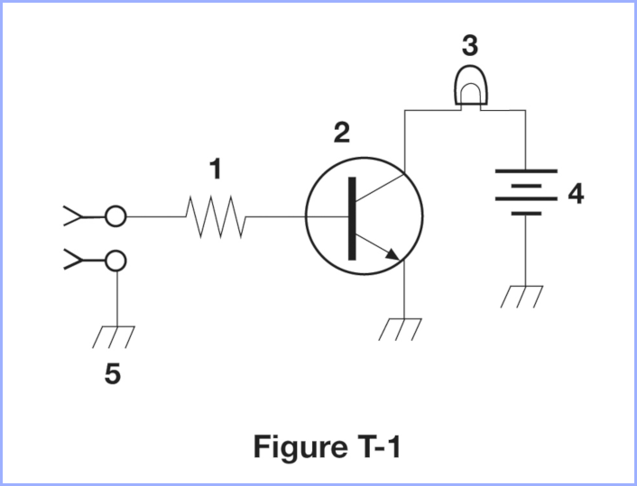
1 - Resistor - This controls, or rather limits, the current flowing into the transistor.
2 - Transistor It is short for "transfer of resistance". Transistors are current operated devices, in that if a small current flows into the Base terminal, shown at the left, and out the Emitter at the bottom, a larger current can flow from the Collector at the top. Transistors operate as both an amplifier and a switch, so if the current into the base is small, then the collector current will be some unknown multiple (a factor of tens or hundreds, varying from device to device, even of the same type) of the input. In this mode the voltage drop across the transistor will be perhaps several volts, and this multiplied by the current generates possibly significant heat. If we ensure the current into the base is adequate, the transistor will go into saturation, with a low voltage drop, reducing the heat wasted. We can tell that the transistor is of the NPN variety, with a positive base to collector current. The clue to this is that the arrow is "Not Pointing iN". The symbol does not indicate the size or capacity of the device, it could be a tiny, low current device, or a large, high current one. Current carrying capacity, and voltage blocking capability are among a transistor's specifications; and there are thousands of variants. Useful ones might be BC-337, or 2N2222A, both in the classic half-cylindrical TO-92 packages. (2N is the US JEDEC system, indicating 2 junctions, BC a European "Proelectron" system indicating that it is a "signal" (lower power) silicon bipolar transistor). Note that the ring is not always used. Old school Germanium transistors use the same symbol, but have either AC, AD, or AF prefixes, or in the earliest cases OC. Power transistors have a metal case, or a plastic case with a metal tab, either allowing heat to be transferred to an aluminium heatsink where necessary.
There are a range of other transistors, such as Field Effect Transistors (FETs), also called unipolar transistors, with high input impedance; and Insulated Gate Bipolar Transistors; plus Silicon Controlled Rectifiers and Triacs.
3 - Filament Lamp - This symbol is not standard, so does not make it clear whether this is an indicator sized lamp, or one designed for illumination. Current flowing flowing through the filament generates a lot of heat, and some visible light, over a broad spectrum. Required current varies from tens of milliamps to 10 amps or more. The questions refer to an indicator lamp, so it is probably a fairly low current lamp. In modern circuits there are often replaced by LEDs, discussed below.
4 - Battery - A battery is actually a "battery of cells", meaning a number of electro-chemical cells connected in series to provide a greater voltage, such as six 1.5 volt cells to make a 9 volt battery, sometimes called a transistor battery, as they will power a transistorised radio. There is no such thing as an AA battery, but an AA cell. Likewise, six 2 volts lead-acid cells makes a 12 volt car battery. Lithium "coin cells" provide 3 volts, various rechargeable lithiums provide around 3.7 volts, with many modern handheld radios using one or two (7.4 volts). NiCad and NiMH provide around 1.2 volts each, six giving 7.2 volts. There are two cell symbols in the symbol, but this does not necessarily indicate that there are two cells in the battery, and the chemistry is also not indicated. The longer line is the positive side. In some drawings the short negative electrode line is made thicker.
5 - Ground Connection - This shows that the terminal or lower connection of the component is connected to what in this case is the negative rail, which may or may not be connected to the case of the device, to earth, or the vehicle chassis. If a negative rail is shown, and such a symbol is used, then it is definitely a connection to the chassis of the device. While symbols are used interchangeably, this one is for a chassis connection, with the earth one being a horizontal line with two shorter ones below it, and maybe a dot.
I probably got a bit over-excited when I originally wrote this, as while it uses concepts on the exam, it goes somewhate beyond it: Specifying the parts would typically work backwards, with either the battery chosen to suit the lamp, or the lamp to suit the supply. Depending on the current, the transistor is then selected, but most silicon NPNs are fine. Unless the transistor is a specialised type, it is best to assume gain of only 20. The junction has a forward voltage drop of 0.6 volts, so apply Vin - 0.6 volts to the R = E / I formula. So, for a 120 mA, 12 volt globe would want 6 mA of drive into the transistor. If we have a 5 volt signal we need R = 4.4 v / 0.006 A = 733.33 ohms, so use a 680 ohm, or 750 ohm, resistor, or a 715 ohm one if you can get it. P = 4.4 x 0.006 = 0.0264 W so a eighth or quarter watt one is fine. Darlington, Field Effect, or Insulated Gate Bipolar Transistors can require a much lower drive current. If the input current is reduced below that required for full brightness, then the transistor will not pass the full current, and so the lamp will glow dimly. This does mean that there is a larger voltage across the transistor, and so it will generate more heat. This is a crude method, as the gain of the transistor varies from device to device, even with the same part number. A better way to vary lamp brightness would be to turn the drive current on and off hundreds of times per second, and vary the duty cycle, something called PWM - Pulse Width Modulation.
This circuit takes a mains voltage input and generates a regulated DC output capable of running a fairly low power device.
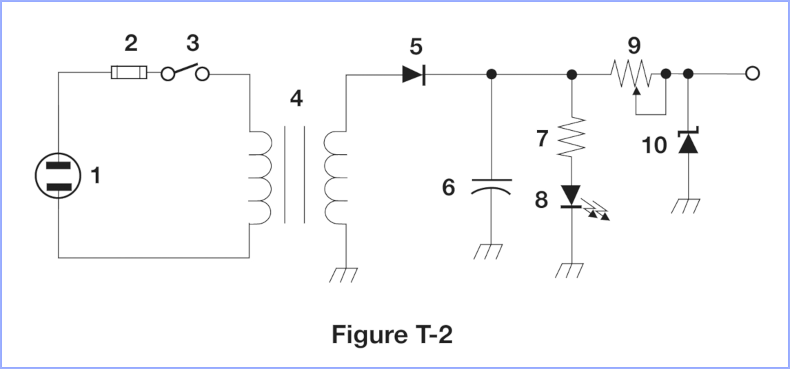
1 - Power Connector - This symbol attempts to replicate the parallel terminals of a US mains plug. The solid rectangles indicate a plug, and by inference it is a non-polarised NEMA 1-15 plug, thus without an earth connection. This is used for 120 volt AC connections at up to 15 amps.
2 - Fuse - Placed as the first component within the device, the symbol emulates a glass or ceramic encased fuse with a metal cap at each end, such as a 3AG sized fuse.
3 - Switch - This turns the device on or off. Specifically, it is a Single-Pole, Single-Throw switch, in that it connects or disconnects a single wire, and only selects 1 output, rather than changing between two or more outputs or inputs. As per convention, the switch operates by the bar moving in a clockwise direction. The type of switch - toggle, rocker, slide, etc is not indicated.
4 - Transformer - The symbol consists of two inductor symbols with a steel laminated core, which is basically what a transformer is, two coils of wire in an iron or steel core. This transforms the 120 volt input to what would usually be a lower voltage. Both the input and output of this transformer is a sinusoidal waveform. Small transformers are also use for electrical isolation between different circuits, while passing signals, useful for things such as connecting PC soundcards to radios for data modes.
5 - Power Diode or Rectifier Diode - A diode allows current to flow in one direction, but not the other. Flow is in the direction of the arrow, and blocked in the other. Small cylindrical diodes are marked with a band at the negative or cathode (K) end. The positive end is the anode (A). The term power means it is designed to carry significant current, rectifier meaning that it rectifies the AC power to DC. Note that this is a simple half-wave rectifier circuit, which would generate a pulse lasting for one 120th of a second (8.333 milliseconds), with a gap of the same duration; the 60 pulses per second are also called 60 Hertz, the US mains frequency. Diodes are rated with the current they can safely carry, and the reverse voltage they can block in the reverse direction. The forward voltage drop of a standard silicon diode is around 0.6 volts. Diodes are marked with either an industry standard number, or a manufacturer's number. This may be a 1N4001, 1N meaning a diode, having a single semiconductor junction, 400x series being the 1 ampere series, and the 1 a peak reverse voltage of rating of 50 volts (35 volts RMS). A more significant supply would use an arrangement of 4 diodes, called a "bridge rectifier" or "full wave bridge", either made from discrete diodes, or within a package. There are also rectifier valves / tubes, generally no longer used, even in valve based equipment, using a totally different symbol.
| The lower 2 devices are 1N4004 power diodes, rated at 1 amp forward current, able to block 400 volts. Maximum AC voltage is 280 volts RMS. The case is a DO-41, aka DO-204AL, with the band indicating the cathode (K). Above this is a 100kΩ 1% resistor, the red indicating a temperature co-efficient of 50 pm/°C Uppermost appears to be a small zener diode, in a glass case. These are mounted on a fibreglass printed curcuit board. You can see the traces through it. |
6 - Capacitor - These devices store energy as an electric charge in the "dielectric" or insulating material between two metal "plates". The implication is that this is an electrolytic capacitor, used to smooth the "lumpy" output of the rectifier to a smooth DC current. The voltage to which it is charges is the peak voltage of the sine wave, which is &sqrt; &root; √2, or 1.4142 times the RMS voltage (less the diode drop). During the reverse mains cycle the capacitor continues to supply current to the load, but discharges to a certain degree, this being the "ripple voltage".
7 - Resistor - As discussed on the last page, these resist the flow of current in accordance with Ohm's Law. The squiggly line is an older symbol, still used in the US. Europeans use a rectangular symbol, more like the fuse one. This would likely be a low powered device of several hundred to a thousand or so ohms. In this case its job is to limit the current through the LED.
8 - Light Emitting Diode (LED) - The flow of current through this device causes the emission of photons of a specific wavelength; in other words, light of a specific colour. The typical LED used as a power indicator, which is the presumed function in this circuit, has a forward current rating to 20 mA, or a little more. They can however be operated at somewhat less than this. The voltage drop at this current is between 1.8 volts (red) to 2.2 volts for yellowish green to 3 or 4 volts for blue and some emerald greens. The permissible reverse voltage is quite low, sometimes around 6 volts. The typical package is a small domed plastic "bulb", 3mm or 5mm in diameter, but there are many others. An alternative symbol is a diode with a lower-case Greek character λ beside it. In many diagrams the component is circled, as the transistor in Figure T-1 is. There are much higher powered LEDs, intended for illumination. A range of standard LEDs are shown below. Click the image to get a bigger photo.
 |
| Click image to enlarge |
Most LEDs here are 5 mm in diameter. The red one second from the left is 3mm. The metal cased ones are very old. Below the coin, the horizontal green one, and rectangular one are both Soviet in origin. The longest leg on the 4 legged one is a common anode or common cathode, the others Red, Green, and Blue, allowing a wide range of colours to be emitted. The LED just left of the coin is a higher current device, the metal helping to remove heat from the diode junction. The yellow star contains a regular 3 mm LED. An Aussie 5 cent coin is 19.41 mm (a bit over ¾").
Your TV remote control uses an Infra-red LED, originally called an IRED (infra-red emitting diode). As the cheap cameras in a 'phone lack an IR filter, you can use a 'phone to check that your remote control is sending IR pulses. Insecurity cameras may include a ring of IR LEDs to provide night-time illumination, and sometimes a dim red glow is visible from these.
Ultra-violet LEDs are also available now, which emit some visible violet light.
Many semiconductor junctions to emit small amounts of light, whether visible or infra-red, as well as being sensitive to light, although the black plastic or metal case protects them from this. Photo-transistors, and photo diodes are optimised to take advantage of this effect to provide light detection. Likewise, solar cells are diode junction which produce usable power when struck by photons.
9 - Variable Resistor - This device consists of a carbon or wirewound resistor element, with a wiper which moves along it connected to the right end. Were the total resistance, say, 100 ohms, this would allow, say a section having a resistance of 57.3 ohms to be selected. However, the person setting this is more interested in the effect the adjustment has on the following components than a particular value, and the resistance value is almost never measured. This component restricts the current flowing beyond this point, to the Zener and the load. While this one might be a larger device, similar ones are used to set various parameters, such as volume in a radio. Often small versions are used within equipment, only adjusted at the factory, or by repair staff.
10 - Zener Diode - This is a special diode, in that while it conducts in the forward direction, if a reverse voltage is placed across it, it regulates the voltage to its nominal voltage. They also have a power rating, such as 1 watt, 5 watts, etc. From this it is possible to determine the maximum current which should be allowed to flow through it. A 5V1 (5.1 volt) device rated at 1 watt can have a maximum of I = P / V = 1 / 5.1 = 196 mA flowing through it. The final element is the output terminal, to which the load is attached.
This simple regulator circuit is a "shunt regulator", as it functions through the Zener consuming power which would otherwise result in the load receiving too great a voltage. As such, these are the most inefficient regulators. If the load were, say an LED based clock, the current drawn would vary between that used displaying six segments at 1:11 and 21 at 18:58, and this unused current would be dissipated as heat in the zener. A modern circuit would use a low cost three terminal IC regulator, such as a 78xx series device. This uses a series pass transistor so the current drawn from the supply is only just over that required by the load, with only a small current used by the internal reference. Regulators also deal with the variation in the supply to the device, be it due to mains variations, or variation from a low car battery, to an overcharging one, around 11 to 15 volts, where a 7808 (8 volt regulator) can be used to supply various audio, frequency generating, or logic parts of the radio with a constant voltage. They also reduce hum due to ripple the ripple mentioned above, when running audio sections of a radio. The other improvement would be to spend under a dollar to use a bridge rectifier. This would reduce the time between charging pulses from the transformer, and thus the ripple voltage significantly. I suppose back in 1968 the three additional brand new 1N4001 diodes cost more than buying a larger "condenser", as capacitors were called back then. Old ways die hard with some people...
Beyond the exam, as well as making a bridge from 4 diodes, you can buy bridge rectifiers pre-build, ranging from the size of an 8-pin IC and up, some bolting to a heatsink.
Exactly what this is is not stated, but it appears to be an antenna matching unit, also called an "Antenna Tuner". Its purpose is to make a transmitter see a 50 ohm impedance, even if the antenna is of a different impedance, or is being used at other than its resonant frequency.
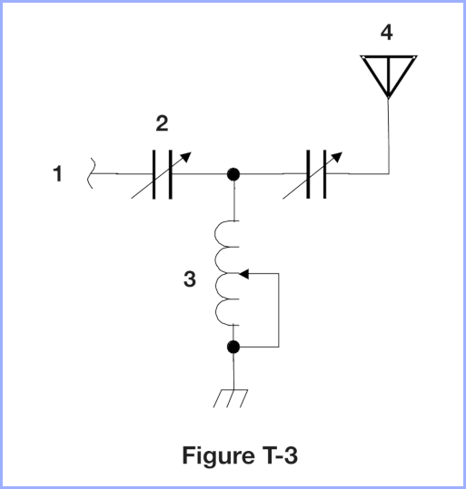
1 - Connector - This is either a physical connector, or perhaps diagrammatic connection from a different part of the diagram, where the designer decided not to draw a line, including if it was from another page.
2 - Variable Capacitor - These usually consist of a metal frame with interleaved vanes, allowing the area interleaved to be varied by rotating a shaft, thereby varying the capacitance. Those used in tuners are similar to those in valve and early transistor radios, but with larger spacing to handle higher voltages.
3 - Variable inductor - An inductor is a coil of wire, tubing or plate material, and this is shown in the emulation of a spiral in the symbol. The arrow indicates that there is some means to tap along the coil. Real life coils tend to avoid shorting the tap to one end, as this interacts with the rest of the coil, unlike shorting the portion of a variable resistor not carrying current. The best variable inductors have the heavy silver-plated coil on a ceramic former, with the whole thing rotating freely, with a pulley-like metal wheel over the thick wire or tube, mounted on a shaft, so the wheel travels the length of the coil, as the coil is turned multiple times. This allows precise selection if the inductance, rather than simply selecting from a few taps. Other variable inductors ware adjusted by screwing a slug of ferrite or similar material in or out of the coil.
4 - Antenna - This symbol is generally used for a wide range of antennas. It emulate an old-fashioned one with fanned-out wires. There are also symbols for dipole antennas, yagis, loops, etc. Clearly, when laying out the physical design of the antenna, this is drawn to scale.
The device also functions as a tuneable high pass-filter, as the higher the frequency, the less the capacitors impede the flow of the signal (lower reactance and thus impedance), and the less the inductor shunts the signal to ground (higher reactance and thus impedance).
Various series or parallel combinations of an inductor with a capacitor are called tuned circuits. These can become resonant at a certain frequency. Transmitters use a similar arrangement, but with the inductors in series with the signal, and capacitors going to ground, so as to act as a low pass filter, reducing harmonics.
Meters - Typically using electromagnetic deflection, a parameter such as voltage, current, or power, can be displayed via the sweep on a meter needle. These can be built into a device, or be stand-along. A device with such a meter, and one or more dials to select the function and range is called a multi-meter. These also measure resistance. In modern equipment a integrated circuit (IC or chip) digitises the voltage, etc, and displays it using seven-segment or other display technology. On radios parameters displayed can include received signal strength, power, supply voltage, SWR (antenna mismatch), and for FM, deviation; in a valve transmitter, plate current may be displayed. The signal strength, or "S-meter" is an exam item.
Relays - While there are a range of relay technologies, the classic version is a switch controlled by an electromagnet. When current is applied to the coil, the magnetic field attracts an iron armature which operates switch contacts. One benefit is that they isolate a low voltage control circuit from a high voltage power one, or occasionally, a high voltage input from a low voltage circuit; in other cases a small current from a switch in the car's cabin operates a relay to turn on high current lamps, or a high-current horn, reducing the length of heavy cable, and I²R losses.
Why are they a "relay", not a magneto-switch, or whatever? The original use was in land-line telegraph, where there was a limit to how far one telegraph station could send a signal to operate the electromagnetic click-clunk sounder at the far station, so initially some poor bunny had to write down the message at a "relay station", often in the middle of the desert, then resend it to the next station. Instead of a sounder, how about making the electromagnet operate a switch automatically?
Not in the test, but large mains relays, often with 240 volt AC coils, are called "contactors". Thus a small timer or switch can turn on a 3-phase bank of heaters in a commercial building.
Integrated Circuits - ICs or silicon chips are devices which combine multiple semiconductor devices, such as diodes and transistors / FETS into one piece of silicon, with resistors, etc, to provide complex functions in one small package.
Linear or analogue ICs include timers, voltage regulators, audio amplifiers, and near complete radio receivers.
Digital ICs include logic ICs, such as AND and OR gates, inverters, counters, going up to microprocessors and microcontrollers - computers on a chip. Logic ICs generally work with voltages at or near the negative and positive supply rails, termed low and high, or 0 and 1.
Off the exam, OR means the outpout is high if one or more inputs are high. For an AND gate this only occurs if both inputs are high. An inverter or NOT gate has an output opposite to the input. NOR and NAND hove outputs which are normally high.
 |
| Standard IC packaging, the Dual-In-Line Package, or DIP , occasionally termsed DIL. The pins are 0.1 inches apart, or 2.54 mm; and the rows 0.3" apart. DIP IC with 24 pins and up are typically 0.6" wide, so this sytle is also called a "Skinny-DIP". It is the civilian black plastic version, there also being white ceramic versions, mostly used by the military. HC indicates that this is a CMOS IC, with this particular design needed a supply between 2 and 6 volts. |
XOR or X-OR gates are high only when a single output is high only when one of the two inputs is high.
Shielded Wire - You may have seen wire, say connecting audio or video equipment which is round, rather then being figure-8 like some charger or lamp cables. You may have noticed such cables sometimes have RCA connector(s) with a pin surrounded by a ring. In these wires a thin central wire is surrounded by plastic insulation, then a layer of bare copper or tinned copper wire "shield", then more insulation (or "sheath"). The idea of this is that the outer layer of wire provides "Faraday" shielding for the inner wire which carries the signal. This style of connection is called "unbalanced", as the signal travels through the single inner, then returned via the shield, which may be earthed. Professional audio systems use "balanced" cable, where the signal is the difference between the two internal wires, and while there is a shield, it is the balance which rejects "common mode" noise. Related is coaxial cable, but the difference is that the ratio of diameters of the inner conductor and the inside of the outer is carefully controlled, as it, along with the type of dielectric material (insulation) affects the characteristic impedance. 75 ohm coax is certainly preferable to thin shielded wire for video signals. Shielded wire also helps stop things such as video signals getting out into audio gear, or causing interference to AM radios. European "CY" power cables have a shield, which, as well as offering physical protection, they also help to contain radio frequency noise or "hash" from variable frequency drives for industrial motors, but this does not improve the current carrying capability of the cable.
These are the actual questions relating to the diagrams above.
T6C01
What is the name of an electrical wiring diagram that uses standard component symbols?
A. Bill of materials
B. Connector pinout
C. Schematic
D. Flow chart
Schematic symbols are part of a schematic diagram, so C.
T6C02
What is component 1 in figure T1?
A. Resistor
B. Transistor
C. Battery
D. Connector
Two terminals, squiggly line, must be a resister. Answer A.
T6C03
What is component 2 in figure T1?
A. Resistor
B. Transistor
C. Indicator lamp
D. Connector
It is a three terminal device, in the form of a bar with three connections made to it, so a bipolar transistor, answer B.
T6C04
What is component 3 in figure T1?
A. Resistor
B. Transistor
C. Lamp
D. Ground symbol
This symbol looks like a small filament lamp, so must be C.
T6C05
What is component 4 in figure T1?
A. Resistor
B. Transistor
C. Battery
D. Ground symbol
The plates of different sizes indicate that this is a battery. The position also suggests that it is the power source for the circuit.
T6C06
What is component 6 in figure T2?
A. Resistor
B. Capacitor
C. Regulator IC
D. Transistor
The symbol with a curved bottom plate is a capacitor, Answer B. Energy is stored as a charge in the dielectric between the plates. In this circuit the capacitor's job is to filter the rectified AC to make a smooth DC supply.
T6C07
What is component 8 in figure T2?
A. Resistor
B. Inductor
C. Regulator IC
D. Light emitting diode
The outward pointing arrows indicate that something is leaving this diode. This something is photons, or light, so Light emitting diode. Answer D.
T6C08
What is component 9 in figure T2?
A. Variable capacitor
B. Variable inductor
C. Variable resistor
D. Variable transformer
The symbol looks like a resistor, but with an arrow to represent the wiper used to tap off a portion of the resistance. A variable resistor, answer C.
T6C09
What is component 4 in figure T2?
A. Variable inductor
B. Double-pole switch
C. Potentiometer
D. Transformer
This is a transformer, answer D. It reduces the AC input voltage to a lower, safer voltage. Others step up to deadly voltages for large valve "linear" amplifiers.
T6C10
What is component 3 in figure T3?
A. Connector
B. Meter
C. Variable capacitor
D. Variable inductor
You see the inductor symbol with an arrow, allowing the inductance to tapped, answer D.
T6C11
What is component 4 in figure T3?
A. Antenna
B. Transmitter
C. Dummy load
D. Ground
This looks like an old antenna, standing up, so A.
T6C12
Which of the following is accurately represented in electrical schematics?
A. Wire lengths
B. Physical appearance of components
C. Component connections
D. All these choices are correct
This shows the interconnections of components, answer C. The same symbol may represent a component almost invisibly small, or the size of a refrigerator.
Huge resistor banks dissipate regenerative braking energy from descending electric trains (for example, at the base of the Blue Mountains) when there is no climbing train to use it. Power factor capacitors at electrical substations are also very large.
There are children's training books which inclue cut-out sheets setting out components following the circuit diagram, using screws and washers into a drilled timber or plastic block to lay out circuits, and this works fine at safe voltages and low frequencies; but this is NOT what the examiner is after.
T6D01
Which of the following devices or circuits changes an alternating current into a varying direct current signal?
A. Transformer
B. Rectifier
C. Amplifier
D. Reflector
The process of converting AC to DC is called rectification, so the component is a rectifier, answer B.
In the telecommunications industry, the whole transformer and rectifier cabinet is the "rectifier", but not what the examiner is looking for.
ICs called operational amplifiers, as they were originally used to perform mathematical functions in analogue computers, can be used to in "precision rectifiers" in measuring equipment, rather than for power. However, if you look at an old-school multimeter, there will often be a separate offset scale, often red, for low AC voltages, due to the voltage drop in the rectifier diode(s) feeding the meter movement.
T6D02
What best describes a relay?
A. An electrically-controlled switch
B. A current controlled amplifier
C. An optical sensor
D. A pass transistor
The classic relay consists of an electromagnetic coil, where current pulls in an iron armature, in turn moving the switch contacts, typically made from springy copper alloys, or springy steel, answer A.
The modern alternative in some applications is the "solid state relay", typically using an internal LED and optical sensor to electrically isolate the input from the mains or other high voltage circuit being controlled, the switching being via silicon switching devices (triacs or fancy insulated gate transistors), so while the last two answers might allude to these, they are NOT the answer sought.
T6D03
Which of the following is a common reason to use shielded wire?
A. To decrease the resistance of DC power connections
B. To increase the current carrying capability of the wire
C. To prevent coupling of unwanted signals to or from the wire
D. To couple the wire to other signals
The intention of the shield is to stop noise and other signals getting into cable, and to stop them escaping, and interfering with other circuits or systems, answer C.
T6D04
Which of the following displays an electrical quantity as a numeric value?
A. Potentiometer
B. Transistor
C. Meter
D. Relay
A meter, whether an electromagnetic movement moving a physical meter needle, or a bargraph or similar arrangement of pixels on an LCD display, can be used to present a range of parameters, including voltage, current, power, SWR, or received signal strength. Answer C.
For signal strength, this is usually against a scale from S1 to S9, then in decibels above this, such as, "10 over 9", 10 dB stronger than S9.
T6D05
What type of circuit controls the amount of voltage from a power supply?
A. Regulator
B. Oscillator
C. Filter
D. Phase inverter
Or better, something like "What controls the voltage output of a power supply?" "Controls" has a similar meaning to "Regulates", and indeed, the answer is voltage regulator, answer A.
This can be a 3 terminal device, often in a TO-220 case with a metal tab which can be bolted to a heatsink; or it can be discreet voltage reference and a pass transistor. It appears the spilers are refering to parts of the more complex "switch-mode" regulator.
T6D06
What component is commonly used to change 120V AC power to a lower AC voltage for other uses?
A. Variable capacitor
B. Transformer
C. Transistor
D. Diode
Note the question asks for a device which outputs an AC voltage, in this case lower than the 120 volt input. This device is the transformer, typically consisting of two (or more) copper coils and some form of laminated steel core, answer B.
T6D07
Which of the following is commonly used as a visual indicator?
A. LED
B. FET
C. Zener diode
D. Bipolar transistor
The only optical device listed is the Light Emitting Diode. Answer A.
T6D08
Which of the following is combined with an inductor to make a resonant circuit?
A. Resistor
B. Zener diode
C. Potentiometer
D. Capacitor
This is the Capacitor, answer D. The circulation of energy between the capacitor and inductor is maximised at resonance, which happens in a correctly adjusted "tuned circuit". Note that resonance occurs at a particular frequency.
T6D09
What is the name of a device that combines several semiconductors and other components into one package?
A. Transducer
B. Multi-pole relay
C. Integrated circuit
D. Transformer
Combined and integrated are similar concepts, so C, the integrated circuit.
"Several" may be anything from a may be something like 20, up to hundreds of billions for flash memory devices.
T6D10
What is the function of component 2 in Figure T1?
A. Give off light when current flows through it
B. Supply electrical energy
C. Control the flow of current
D. Convert electrical energy into radio waves
This is a three terminal device, the transistor, and its job is to switch or control the flow of current, answer C. It is connected via the resister to an external voltage or current source of some kind, and the current from this, when present, causes the transistor to allow current to flow from the battery via the lamp.
If the input current is low, it would cause the current flow to be restricted, so the lamp glows dimly, but such as simple circuit is s very poor way to do anything other then fully on, or fully off.
Ideally, the answer would continue "under the influence of the input signal".
T6D11
Which of the following is a resonant or tuned circuit?
A. An inductor and a capacitor connected in series or parallel
B. A linear voltage regulator
C. A resistor circuit used for reducing standing wave ratio
D. A circuit designed to provide high fidelity audio
Resonant circuits consist of an inductor and a capacitor, and these can be in series or parallel, so A is the answer.
These are two circuits which are beyond this paper, but are somewhat interesting.
 |
This circuit is a simple logic element, the inverter or NOT gate. While we have seen the transistor conducting a load current, the lamp in the circuit above can be replaced with a resistor, and a low power output taken from the collector pin. The Output will be pulled HIGH by the 1.5 kΩ resistor when the Input X has no voltage applied, meaning it is LOW The transistor is not conducting. If the LED is not present, then the voltage at the output will be the positive rail voltage. If a voltage (a HIGH signal) is applied to the Input X, the transistor will conduct, and the output will be pulled LOW. The diodes form an OR gate, meaning that if a voltage is applied to either A OR B, or to both, then a voltage will appear at X, which will operate the transistor. Together this circuit is a NOR gate, meaning an input on either A or B will extinguish the LED. The diodes can be power diodes, or 1N4148 or similar signal diodes. |
 | If the diodes (including the LED) are removed form the above, and a variable voltage or audio is applied to the input, the output voltage can be made to vary, forming a simple (and sub-optimal) amplifier. The amplifier may be improved with resistors to correctly bias the base, these being R1, R2, and RE. C1 isolates the DC bias from the input, and C2 isolates the DC element of the output from further stages. The variation in voltage at the input causes a variation in the current flowing from the base to the emitter. This causes a greater variation in the current flowing from the collector to the emitter. Georg Ohm, perhaps standing on his head, tells us that varying the current through a resistor varies the voltage across it. Thus the output in a reproduction of the input, but with a greater amplitude or voltage swing. It is inverted, indicated by the ∿ waveforms, but that generally does not matter. RE and CE improve stability and performance. This is said to be a Class A amplifer, as current is always flowing in RL. This amplifier might be used to increase the signal coming from a microphone, to feed a modulator; or it can be used to increase the signal coming from a detector or discriminator in a radio receiver, to feed the speaker amplfier. |
Note that an inverter which converts a DC supply to an AC one is somwewhat more complex than this.
On to the next lesson: More on Components
You can find links to lots more on the Learning Material page.
Written by Julian Sortland, VK2YJS & AG6LE, January 2022.
Tip Jar: a Jefferson (US$2), A$3 or other amount / currency. Thanks!