Home - About AR - Learning Material - Exams - Clubs - Posters
For DC we know power is voltage x current, and we should also know that we can apply this to something like an AC mains powered bar heater, in which the heating coil is not overly inductive, with reasonable accuracy, or even a fan heater, in which the motor current is trivial compared to the element current.
However, if we have a large textile factory, where the primary load is the motors of the looms, the current will lag the voltage, giving a poor power factor. This means that current flows in and out of the motors windings with some of it not doing work. The angle of the lag determines the power factor.
The power company will be unhappy about having to supply current which is not doing work, and so not being charged for if a standard meter is used. Off the exam, when inductive loads, such as motors and transformers are lightly loaded, the power factor generally becomes worse. Also, the current which flows due to a poor power factor does cause I²R losses in building, street cabling, and transformers.
The power factor is calculated as the Cosine of the phase angle. The first 90 degrees of a cosine wave starts at 1, and declines towards 0 at 90 degrees, following the curve of the second 90 degrees of a sine wave. If the value is negative, the same power factor (the same cosine value) is produced as if it were a positive value. In other words, -30 degrees, like +30 degrees, is around 0.866. The value must between 1 (purely resistive) and 0 (purely reactive). Real world power loads tend to have some inductive component, so a PF of between maybe 0.7 and 0.95.
Apparent power is measured in VA, or Volt Amps. You may have seen a large ground-mounted street transformer marked 750 kVA, or a range of transformers marketed by their VA value, such as 300 VA toroidal units to power large audio amplifiers. The typical "pole pig" ranges from a few tens of kVA to a few hundred. This is because it is the amps flowing in the load which heats the windings. So, if the load is a non-inductive resistor, VA can equal the power of the load in watts, but if the load is inductive, or capacitive, this is not the case.
When doing the cosine (or other calculations), ensure your calculator is set to degrees, often indicated by a "DEG" sign; or by the lack of a RAD marker, indicating Radians.
There are 2π radians in one circle, and rotation velocity or frequency can be indicated in radians per second, marked with a lower case omega, ω. You will this see ω replacing 2π𝑓 in formulas such as: XL = 2π𝑓L = ωL. Radians per second also used in Physics, in place of RPM.
As a reminder, we key in 30 and press [COS] to get a value, which if necessary, we can multiply by volts and amps.
Off the exam, the power company supplying our factory may require we place large power factor correction capacitors. These may be the size of a midi-tower PC. Smaller units are used inside fluorescent lamps in businesses and colleges, to correct for the large inductance in the ballast. Ceiling fans in commercial premises also contain them. All these capacitors, if older, may contain oily Polychlorinated Biphenyls, or PCBs, a significant toxin and pollutant.
Also off the exam, but some libraries lend out what are claimed to be power meters. They are however some sort of current meter, using an assumed or measured voltage to display what is actually Volt-Amps, failing to take PF into account. Thus the small capacitive current flowing in the lead to a lamp will show as power consumption, even though this will NOT turn a proper power meter.
Power is simply the number of volt-amps muliplied by the power factor: P = E × I × Cos ϕ
Several important values are:
| Angle | Exact | Decimal | Comment |
| 0 | 1 | 1.0 | Purely resistive |
| 15 | (√6 + √2) / 4 | 0.9659 | Similar to 14° on previous page |
| 30 | √3 / 2 | 0.8660 | |
| 45 | √2 / 2 | 0.7071 | Also 1 / √2 |
| 60 | 1/2 | 0.5 | |
| 90 | 0 | 0 | Purely reactive |
We may remember that a position on a map can be described as being 5 kilometres north, and 8 kilometres east of our position; or we can say that it is 9.434 km away, on a bearing of 57.995 degrees.
It is important to remember that while we can describe an antenna as having an impedance of 56+j27 at one frequency, at another it may be 47-j12, and thus the antenna tuner will need significantly different compensation elements. While this may be more noticable using an antenna on different Amateur bands rather than across a single one, within the AM broadcast band, which has a ratio of over 1:3 in frequency, if we wish to combine two transmitters into one mast, we need fairly complex matching networks, and for 5-10 kW the coil might be the size of a 8 to 10 litre paint tin.
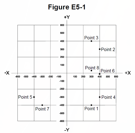
Figure E5-1 shows a graph with real (X) and imaginary (Y) axis. The real, resistive, component must be positive, in the right part of the graph. The imaginary or reactive component may be positive if the reactive part is inductive, and negative if it is capacitive.
These are the actual questions from the Extra licence exam pool, as published by the NCVEC.
E5C01
Which of the following represents a capacitive reactance in rectangular notation?
A. –jX
B. +jX
C. Delta
D. Omega
Capacitance has a negative sign, so it is -jX, answer A.
E5C02
How are impedances described in polar coordinates?
A. By X and R values
B. By real and imaginary parts
C. By phase angle and magnitude
D. By Y and G values
By phase angle and magnitude, answer C.
E5C03
Which of the following represents an inductive reactance in polar coordinates?
A. A positive magnitude
B. A negative magnitude
C. A positive phase angle
D. A negative phase angle
Polar notation requiers a phase angle, and for inductive circuits this is positive phase angle, answer C.
E5C04
What coordinate system is often used to display the resistive, inductive, and/or capacitive reactance components of impedance?
A. Maidenhead grid
B. Faraday grid
C. Elliptical coordinates
D. Rectangular coordinates
Rectagular coordinates use two figures, one for the resistive component, the other for the reactive, answer D.
E5C05
What is the name of the diagram used to show the phase relationship between impedances at a given frequency?
A. Venn diagram
B. Near field diagram
C. Phasor diagram
D. Far field diagram
Phase relationship just might be shown on a phasor diagram. Yes, it is answer C.
E5C06
What does the impedance 50–j25 represent?
A. 50 ohms resistance in series with 25 ohms inductive reactance
B. 50 ohms resistance in series with 25 ohms capacitive reactance
C. 25 ohms resistance in series with 50 ohms inductive reactance
D. 25 ohms resistance in series with 50 ohms capacitive reactance
The real component is 50, and that represents the resistance of 50 ohms, and the imaginary (j) component is the reactance, and being negative, this is capacitive; so 50 Ω resistive and 25 Ω capacitive reactance, answer B.
E5C07
Where is the impedance of a pure resistance plotted on rectangular coordinates?
A. On the vertical axis
B. On a line through the origin, slanted at 45 degrees
C. On a horizontal line, offset vertically above the horizontal axis
D. On the horizontal axis
As there is no reactive component, the point is on the horizontal axis, answer D.
E5C08
What coordinate system is often used to display the phase angle of a circuit containing resistance, inductive and/or capacitive reactance?
A. Maidenhead grid
B. Faraday grid
C. Elliptical coordinates
D. Polar coordinates
The term "phase angle" is the indication that this is is polar coordinates, answer D.
E5C09
When using rectangular coordinates to graph the impedance of a circuit, what do the axes represent?
A. The X axis represents the resistive component and the Y axis represents the reactive component
B. The X axis represents the reactive component and the Y axis represents the resistive component
C. The X axis represents the phase angle and the Y axis represents the magnitude
D. The X axis represents the magnitude and the Y axis represents the phase angle
The horizontal X axis is the resistive component and the vertical Y axis is the reactive component, answer A.
E5C10
Which point on Figure E5-1 best represents the impedance of a series circuit consisting of a 400 ohm resistor and a 38 picofarad capacitor at 14 MHz?
A. Point 2
B. Point 4
C. Point 5
D. Point 6
This is a capacitor, so its reactance must be negative on the vertical (Y) axis, and 400 on the X axis, and the only point appearing to fit this is Point 4, answer B.
However, we better prove it, as if the frequency and capacitance were both large, then Xc would be close to zero (around Point 6).
XC = -1/(2π𝑓c) = -1 / (2xπ × 14×106 × 38×10-12) = -1 / 6.283185 × 0.000532 = -1 / 0.003342655 = -299.16 ohms.
E5C11
Which point in Figure E5-1 best represents the impedance of a series circuit consisting of a 300 ohm resistor and an 18 microhenry inductor at 3.505 MHz?
A. Point 1
B. Point 3
C. Point 7
D. Point 8
Being inductive, the Y component must be positive, and the resistance (the X axis) is 300, so there are two possible choices.
XL = 2π𝑓L = 2 × π × 3505000 × 18×10-6 = 6.283185 × 63.09 = 396.406 ohms, so point 3, answer B.
E5C12
Which point on Figure E5-1 best represents the impedance of a series circuit consisting of a 300 ohm resistor and a 19 picofarad capacitor at 21.200 MHz?
A. Point 1
B. Point 3
C. Point 7
D. Point 8
Being Capacitive, the Y component must be negative, and the resistance (the X axis) is 300, so it can only be point 1, answer A.
XC = -1 / (2π𝑓C) = -1 / (2 x π × 21200000 × 19×10-12) = -1 / (6.283185 × 4.028×10-4) = -1 / 2.530867042×10-4 = -395.15071312 ohms.
E5D01
What is the result of skin effect?
A. As frequency increases, RF current flows in a thinner layer of the conductor, closer to the surface
B. As frequency decreases, RF current flows in a thinner layer of the conductor, closer to the surface
C. Thermal effects on the surface of the conductor increase the impedance
D. Thermal effects on the surface of the conductor decrease the impedance
Kicking in even at mains frequencies, as the frequency increases, the current flows in a thinner and thinner layer, closer to the surface, and is significant at high-HF bands, and up, answer A.
I read that using "Copperweld" or similar copper-clad steel wire for antennas for 10 metres is great, as the current flows in the copper, but at 3.5 MHz, resistance of the underlying iron core comes into play.
E5D02
Why is it important to keep lead lengths short for components used in circuits for VHF and above?
A. To increase the thermal time constant
B. To avoid unwanted inductive reactance
C. To maintain component lifetime
D. All of these choices are correct
Component leads in a VHF+ circuit become inductive factors, so need to be kept short, answer B.
E5D03
What is microstrip?
A. Lightweight transmission line made of common zip cord
B. Miniature coax used for low power applications
C. Short lengths of coax mounted on printed circuit boards to minimize time delay between microwave circuits
D. Precision printed circuit conductors above a ground plane that provide constant impedance interconnects at microwave frequencies
These are precisely dimensioned conductors printed on special PCB material, above a ground plane, typically to provide constant impedance interconnects on microwave boards, answer D.
In serious equipment the substrate / insulation material can be Alumina (Aluminium Oxide) or a ceramic. At these frequencies U-shaped tracks and similar features can be used as filters, and importantly, corners in the tracks must have 45 degree bevels, as otherwise the signal bounces back!
E5D04
Why are short connections used at microwave frequencies?
A. To increase neutralizing resistance
B. To reduce phase shift along the connection
C. To increase compensating capacitance
D. To reduce noise figure
Say at 10 GHz, the wavelength is a mere 3cm, so a few millimetres in like a lead metres long within an HF radio, something avoided in all but the most massive transmitters, and so at these frequencies, even a lead a few millimetres would cause a phase shift, answer B.
At 47 GHz a wavelength is just 6.3 mm!
E5D05
What is the power factor of an R-L circuit having a 30 degree phase angle between the voltage and the current?
A. 1.73
B. 0.5
C. 0.866
D. 0.577
Pull out the calc, and find that COS 30 = 0.866025404, answer C.
E5D06
In what direction is the magnetic field oriented about a conductor in relation to the direction of electron flow?
A. In the same direction as the current
B. In a direction opposite to the current
C. In all directions; omni-directional
D. In a circle around the conductor
This is in a circle around the wire, answer D.
The previous version refered to the "Left hand rule", which you may rememeber form high school. You can work out the atracting and repelling forces in parallel or reverse parallel conductors using it. Greater currents generate greater forces.
E5D07
How many watts are consumed in a circuit having a power factor of 0.71 if the apparent power is 500VA?
A. 704 W
B. 355 W
C. 252 W
D. 1.42 mW
Just multiply the PF by the VA value, and get P = 0.71 x 500 = 355 watts, answer B.
Power, in watts, must be less that or equal to the VA figure, as PF cannot exceed 1 (perfectly resistive).
This would occur with an angle of (just under) 45 degrees, famous for being 1/√2 ≈ 0.70710678118.
E5D08
How many watts are consumed in a circuit having a power factor of 0.6 if the input is 200VAC at 5 amperes?
A. 200 watts
B. 1000 watts
C. 1600 watts
D. 600 watts
A question designed to be answered without a calculator, as 200 × 5 is 1000 VA, and this multiplies by 0.6 to become 600 watts, answer D.
E5D09
What happens to reactive power in an AC circuit that has both ideal inductors and ideal capacitors?
A. It is dissipated as heat in the circuit
B. It is repeatedly exchanged between the associated magnetic and electric fields, but is not dissipated
C. It is dissipated as kinetic energy in the circuit
D. It is dissipated in the formation of inductive and capacitive fields
The energy "sloshes" between the magnetic and electric fields, meaning between the coil and the capacitor, answer B.
E5D10
How can the true power be determined in an AC circuit where the voltage and current are out of phase?
A. By multiplying the apparent power times the power factor
B. By dividing the reactive power by the power factor
C. By dividing the apparent power by the power factor
D. By multiplying the reactive power times the power factor
This is simply multiplying the apparent power by the power factor, answer A.
E5D11
What is the power factor of an R-L circuit having a 60 degree phase angle between the voltage and the current?
A. 1.414
B. 0.866
C. 0.5
D. 1.73
Firstly, you can ignore anything outside the 0 to 1 range, but COS 60 (degrees) is 0.5, answer C.
E5D12
How many watts are consumed in a circuit having a power factor of 0.2 if the input is 100-VAC at 4 amperes?
A. 400 watts
B. 80 watts
C. 2000 watts
D. 50 watts
This is P = E x I x Cos ϕ = 100 x 4 x 0.2 = 400 / 5 = 80, answer B.
E5D13
How much power is consumed in a circuit consisting of a 100 ohm resistor in series with a 100 ohm inductive reactance drawing 1 ampere?
A. 70.7 Watts
B. 100 Watts
C. 141.4 Watts
D. 200 Watts
P = I²R = 1² x 100 = 1 x 100 = 100 watts, answer B.
Note that, save for slight losses due to the resistance of the copper, etc, in inductors, power is only dissipated in resistors. No matter what the surrounding components are doing, 1 amp through the resistor causes the same dissipation. There would however need to be greater than 100 volts across the entire circuit to drive this current trough the resistor.
E5D14
What is reactive power?
A. Wattless, nonproductive power
B. Power consumed in wire resistance in an inductor
C. Power lost because of capacitor leakage
D. Power consumed in circuit Q
This is wattless, nonproductive power, answer A.
E5D15
What is the power factor of an R-L circuit having a 45 degree phase angle between the voltage and the current?
A. 0.866
B. 1.0
C. 0.5
D. 0.707
The power factor is the cosine of the angle, so whip out the calculator, bang in 45, hit COS, and get 0.707106782, answer D.
In Australia, with the current blame-game on power prices (and lying about the cost of renewables), remember that 9.1% of the price you pay is the right-wing mob's GST! The same concept (but a different figure) applies in other countries with consumption tax such as VAT, MOMS, GST, etc.
On to: Components 1 - Semiconductor materials & devices; Diodes
You can find links to lots more on the Learning Material page.
Written by Julian Sortland, VK2YJS & AG6LE, June 2022.
Tip Jar: a Jefferson (US$2), A$3 or other amount / currency. Thanks!