Home - About AR - Learning Material - Exams - Clubs - Posters
Amateur Radio Info & Exams - Ohm's Law and Power
For exams 1 July 2022 to 30 June 2026.
The changes in this question pool are a few small language simplifications; conversion of ohms law from a written description of the formula to the actual formula; and some somewhat out-of-date pedantry, with phase modulation (PM) added to the FM answers. Reference to Kirchhoff's laws have been removed from the questions, but the concepts still apply. (Don't worry if this doesn't mean much yet).
I'll start with the section on voltage and the flow of current, or electric power.
Ohm's Law
Ohm's Law and the power calculations are inter-related calculations which can tell us about how energy is being used in a circuit. Each one involves a simply multiplication or division relationship.
The voltage is the driving force in a circuit, and in normal circuits this is a few volts, a few tens of volts, or a few hundred volts. Examples are 3 volts in a flashlight, 12 volts in a dinosaur juice car, or 120 and/or 240 volts in household power.
Current is the flow of electrical energy, expressed in Amperes, or Amps. A small LED (light emitting diode) used a few milliamps (a few thousands of an Amp) up to 20 mA. A ham radio in a car might draw a few hundred mA on receive; and a few amps, or up to 25 amps while transmitting.
In simple circuits, resistance controls the current flow, and is expressed in Ohms.
If high school physics is still bouncing around in your head, in most cases we are discussing conventional current, from positive to negative, rather than electron flow.
Parallel and Series Circuits
At your house the various lights can be switched on and off independently, or perhaps a couple of lights are operated by one switch. Either way, each lamp is in parallel with the others, and in Australia each has 240 volts across it, or 120 volts in the US. Likewise, radios and accessories are placed in parallel across a mains powered 13.8 volt supply, or a 12 volt battery, and the current summed.
A series circuit is one in which current flows from one device to the next. In old-style Christmas tree lights, typically twenty little 12 volt lamps are in series across 240 volts, meaning no transformer is needed, but removing one lamp means the whole string goes out.
Another example is a resister feeding an LED, a red or green LED only needing ~2 volts, so 3 volts must be dropped if using a 5 volts supply. If a switching a transistor, its voltage drop must be taken into account, especially if the supply voltage is low. A few "white" LEDs can be put in series across a 12 volt supply (with a resistor), as due the the physics of the internal diode junction, each needs around 3 volts (these are usually a blue LED with a yellow phosphor). The same is done in a small neon indicator for your oven, where a high value resistor limits the current through the neon lamp, rated for around 90 volts, and thus 150 volts is dropped in the resistor.
Down-under, for some stage lighting, two 120 volt 1000 watt PAR 64 lamps are (were) put in series across 240 volts. House lighting at the Sydney Opera House also used them in pairs.
The forward voltage on an LED varies depending on colour, material used, and follows a "curve", so as current rises from 1 mA to 25 mA, it rises by a few tenths of a volt.
Additional Parallel and Series Circuit Info
A dude called Kirchhoff worked out some of the basic rules about these circuits. They can be paraphrased as saying that, for DC circuits, the current in all elements of a series circuit is the same, and that the voltage across all components in a parallel circuit is equal. Put a radio and a lamp across a 12 volt battery and both have 12 volts across them. At the component level, if a resistor of the appropriate value and rating feeds a zener diode, it will clamp the voltage at a specific level. If a small load is placed across the diode, then it will have the voltage of the zener applied to it. This is a very simple shunt voltage regulator. The current in the resistor is equal to the sum of that in the zener, and that in the load.
When two components are in parallel, the current flow in each is determined by the value (resistance, etc) of that device. If the devices in parallel are fed from a current source, which can be as simple as a 12 volt battery and a resistor, then the two devices interact more. If two LEDs are placed in parallel, the one with the lowest forward voltage drop will take most or all of the current, which is why LEDs should not be connected this way, as there are variations, even between ones with the same part number. If a current source of 30 mA has a 200 ohm resistor, and a 100 ohm resistor across it, then the 100 ohm one will take two-thirds of the current, the 200 ohm one one-third.
When two are in series, the voltage across each is determined by the relative values, or nature of the devices. A simple example is the voltage divider. In some circuits, rather than the absolute value we get with a zener, or voltage reference diode, we want a percentage of the supply voltage (although we can also take this from a regulated or reference voltage). Beyond the exam, one example is in timing circuits where we want a reference of (about) 63.212% of the supply voltage, as we can easily predict how long a capacitor takes to charge to this percentage of the supply voltage. One time-constant (τ), is determined by multiplying the resistance by capacitance.
At AC or RF frequencies components such as inductors and capacitors in series or parallel can interact in more complex ways.
DC & AC
DC is direct current, where the current travels in one direction only, from positive to negative. This is derived from batteries, or solar panels. Electronic devices require DC.
AC is alternating current, where the current travels backwards and forwards, usually derived from rotating generators. The big benefit is that it is possible to increase or decrease the voltage using transformers.
A simple diode, or diode bridge, is all that is needed to convert the AC output of a transformer to rough DC, with a capacitor to smooth it.
Making AC from DC requires a more complex "inverter" circuit, consisting of an oscillator, and power transistors to switch current through various transformer windings.
Comment on Maths
When I started high school I was a little worried about Algebra, but then I realised that 5 + x = 12 was just a grown up version of 5 + ▢ = 12, and instead of mentally calculating 7 to write it in the box, you rearrange the equation to x = 12 - 5, then calculated that x = 7. You will see that on one side I removed, or subtracted, the 5, so on the other I had to subtract 5.
Note however most calculations here are multiplication and division. Note that the slash thus / means division, and this is used in the new version of the exams.
The use of a simple or scientific calculator is permitted, as long as it is non-programmable, and not part of a 'phone or PC. However, in the Technician paper the maths is simple enough that many won't need one.
The typical paper only includes a few maths questions, and stuffing them up is unlikely to make you fail the paper.
Power Calculations
If you are in Australia or NZ, you may have turned over a power board or power strip, and seen "Maximum 240 VOLTS - 10 AMPS - 2400 WATTS", or when buying a heater saw the that the largest retail model was 2400 watts. Why those numbers? The standard power outlet gives 240 volts*, and the standard outlet is rated at 10 amperes, or amps. Multiply those out, and you get the maximum heating capacity, or maximum work a motor can do, 2400 watts. If you are American you would multiply out 120 volts and 15 amps, getting just 1800 watts (but there are options to get more power, like 20 amp or larger outlets, or HOT to HOT 240 volt ones; (and industrial 277 / 480 volt three-phase)).
*You will sometimes read about 230 volts. 230 volts is now the offical voltage in most developed countries. In Australia, and the UK there is large upward tolerance, meaning the real voltage is often the traditional 240 to 250 volts. In parts of Europe there is a large downward tolerance, permitting the ongoing use of 220 volt systems.
Voltage is also called "Electromotive Force", or EMF. It is measured in volts, and while battery and mains voltages use units, signals in radio receivers and the like can be millivolts (mV) or microvolts (μV); and voltages inside big valve based power amplifiers and power transmission lines can be kilovolts (kV), or even a megavolt (MV) in the latter case. Higher voltages may require thicker insulation. In formulas voltage is usually represented by E for EMF, except sometimes when a voltage-drop is being calculated, and V is used. Europeans may use U for voltage.
Voltage can also be termed "electrical pressure", as its function is similar to water pressure, driving flow.
For these basic power calculations it does not matter if the power is AC or DC.
Current is the flow of electrical charge, noting that while conventional current flows from positive to negative, after this was established, it was found that electrons actually travel from negative to positive. Incidental, while an electrical pulse travels at close to the speed of light, electrons themselves travel fairly slowly. Current is measured in Amperes, or Amps (A), and amp being the transfer of one coulomb per second. Small electronic equipment typically only needs fairly small current, of tens to a few hundred milliamps (mA), while a mobile transceiver 10 to 20-odd amps while transmitting. Starting a car requires hundreds of amps. Kiloamps (kA) are only used on things like smelting aluminium. Maximum fault current breaking ratings of circuit breakers are also in kA. In formulas I is used.
Large, high voltage capacitor banks can be used to pass very short, very high current pulses, which generate powerful magnetic fields, capable of pinching or crushing cola cans. Such currents can also cause significant damage to equipment, generate blinding and burning flashes, and spray molten metal.
Thinking back to your physics class, but off the exam, 1 ampere is 1 Coulomb of charge flowing per second. Now forget that, as that word is only used as an incorrect answer below.
Current has several useful effects. As the electrons collide with others in the material, it heats the material it flows through, a process called Joule heating. Special resistive metal alloys are used to heat air, water, or food. In a toaster it is the radiating infra-red energy which does at least part of the toasting. At high temperatures the wire becomes yellow or white hot, as in a light globe / bulb / lamp. The downside is that even copper wiring can become warm, wasting energy. Another effect is that current generates magnetism, useful in everything from a simple electromagnet (used in solenoids and relays) to meters to motors to most speakers, with the reverse effect used in "dynamic" microphones, converting audio energy to a small electrical signal. Current in special diode junctions produced visible or infra-red light; and through gases, visible or UV light. Certain crystals also deform if current is passed through them (and can generate electrical pulses if struck). There are also electro-chemical effects, useful in things like electroplating, and batteries.
Power is the rate of use of energy, and 1 watt is 1 joule per second. One watt is also 1 volt at 1 amp, or any equivalent, be it 3.3 volts at 300 mA, or 12 volts at 83.3 mA. A wide range of sub-multiple and multiples apply, from femtowatts to gigawatts (as I write this Australia is using somewhat over 25 GW of power). Light globes are marked in watts, based on the power they consume, from tens to a hundreds of watts, to thousands for stage and film lighting. RF power is measured in mW, W, kW or MW, with the power limit for most ham bands being 1500 watts, or 1.5 kW. Technicians are allowed "only" 200 watts of CW on HF, more than allowed by "full-call" or Advanced licence holders down-under*! Resisters and various semiconductors are also rated by their maximum safe power dissipation. Watts and various multiples can be applied to other things, such as the output of a petrol or diesel engine, given in kW, or even an athlete or cyclist. P is used.
* For Morse code (CW), AM, and FM, the power limit in Oz is 125 watts, with 400 watts peak envelope power (PEP) applying to Single Side Band (SSB).
The formulas, for solving the different values are:
P = I × E
I = P / E
E = P / I
If a charging 'phone draws 2.1 amps at 5 volts, how much power is being delivered to it?
P= I × E
P = 2.1 × 5
P = 10.5 watts.
The new exam has change questions from a how much power a device is "using" to the amount of power the supply is "delivering".
If a globe is rated at 21 watts at 14 volts (the real voltage in a running car), the current draw is:
I = P / E
I = 21 / 14
I = 1.5 amps.
Suppose you used a clamp meter to test an industrial heater marked 5 kW and found it was drawing 18 amps. What voltage is its supply?
E = P / I
E = 5000 / 18
E = 277.7777 volts
Thus, the supply is nominally 277 volts (the single phase voltage of a US 480 volt delta system).
Watts or Volt-Amps?
You will see a transformer rated in VA, rather than watts. This is because with AC the current is not always in phase with the voltage, due to inductive or capacitive loads, and while true power (watts) is less than the apparent power (VA), the A (current) in the calculation does cause I²R heating in the windings (see below). Understanding leading and lagging currents is only required for the Extra paper.
Resistance and Ohm's Law
But what determines how much current flows?
The overall resistance of the circuit determines how much current flows at a certain applied voltage. Resistance in the opposition to the flow of current with in a circuit. Sometimes it is deliberate and desirable, and other times it is not. If we are powering an LED (light emitting diode) we need to limit the current, or the LED has a brilliant, but very short career. In this case we use a resistor made from a film of carbon, or a film of metal, over a ceramic form. Excess energy is dissipated as heat, but the overall efficiency of a LED is often better than a small lamp, and reliability greater. Larger resistors are made by wrapping wire made from alloys such as one of nickel and chromium, termed Nichrome, onto a ceramic form.
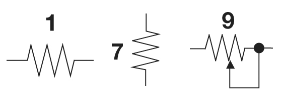
Above are the resister symbols used in the examination for sighted candidates, snipped from the circuit diagrams. The first two are fixed resistors, the third a variable resistor. The arrow represents the wiping terminal moving along the track of resistive material, or from winding to winding of a wire-wound resistance wire coil or toroid. The wire-wound version is also called a rheostat (not in the exam). The device is often called a potentiometer, I think as if you were to put one outer terminal to ground, the other end to, say 10 volts, then the rotating the shaft would vary the voltage on the centre terminal between 0 and 10 volts, that is, varying the potential, as voltage is also called. They can be used as a volume control, or to control a wide range of parameters.

Above are three fixed value resistors. An Aussie 5 cent coin is 19.41 mm (a bit over ¾").
- The top resistor is beige, indicating it is carbon film, reading right to left, Brown-Black = 10, Yellow meaning 4 more zeros (or x10 to the 4), so 100,000 ohms, or 100 kΩ; Gold means ±5% tolerance.
- Below it is a blue resistor, indicationg metal film construction, Orange-Grey-Orange = 383, Black meaning no further zeros (x1, as 10&sup0; is 1), so 383 ohms, Purple means ±0.1% tolerance.
- Last, the military grade DALE metal film resistor is marked 6650F, meaning 665 × 10^0 = 665 Ω and from the Internet, F = ±1% tolerance.
Note that any positive number raised to the power of zero is one.
The civilian resistors above are rated at around ¼ or 0.25 watts. For maximum reliability, the military one is rated just ⅛ or 0.125 watts, despite its commercial cousin being able to handle ½ or 0.5 watt. That said, at civvy ratings, these devices will become too hot to touch!
Modern equipment often uses tiny surface mounted components, soldered directly to the circuit board, measuring from under 1 mm long, up to 6.3 × 3.2 mm.
Even copper has some resistance, and thus there are limits on how much power a certain size wire can safely carry, lest it overheat, and the insulation melt, smoke, or burn. The best conductor is silver, and this is used as a plating in specialised coaxial cable, and in inductors in some high current RF circuits. Isn't gold the best? Nope, it just looks pretty on audiophile connectors. Where high reliability is needed, gold's resistance to corrosion is valuable. Iron and steel are poor conductors, but stainless can be used in electric fence tape, where high voltage means resistance is not a major problem. Aluminium is not quite as good as copper, but is cheap, even though a greater cross-section is needed. Its use is popular when copper is expensive, but special care must be taken to ensure the natural protective oxide layer is correctly pierced, lest a high-resistance joint is made, which later causes a house fire, etc.
The unit of resistance in the ohm, using the symbol uppercase Omega, thus: Ω. As early computers didn't always handle Greek, R was used, or when a multiplier was used, the multiplier was used alone. Also, the decimal is often replaced by the unit, or multiplier. The unit can be used to measure both the resistance of a length of wire, for example, or of the resistors mentioned above. In a circuit or notes, a 5.6 ohm resistor may be listed as 5.6Ω, 5.6R, or 5R6; a 2.7 kilohm one listed as 2.7kΩ, 2.7k, or 2k7; and 8.2 megohms can be 8.2M&Omega, 8.2M, or 8M2. Special resistors push up to Gigohms. There are also low resistance resistors, both small electronic components, and large stainless steel or iron units. For example, 100 milliohm is 100 mΩ, but may be written 0.1 Ω or 0R1.
Omega is the last letter of ancient and modern Greek alphabets, and thus also has connotations relating to the last item, or the end. It shares the standard short o sounds with Omicron in the modern language, but was a longer sound in the original. The lower case version is ω, refering to rotational velocity.
A volt will push one amp through a 1 ohm resistor. The formula is:
E = I × R
I = E / R
R = E / I
The proper Irish name of Ireland is EIRÉ, so remember, E=IR.
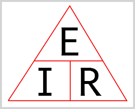
The diagram above is another memory aid. Cover the value you want to find, and either multiply or divide, depending in whether the remaining symbols are beside or over each other.
Note that I have used / as the division symbol, as often used in computing instead of ÷ for simplicity. In many papers you will see formulas with the symbols to be multiplied strung one after the other with no symbol, or occasionally with just a dot between them; and in programming, the asterisk, *.
If we wanted to push 2 amps through a 5Ω resistor, we need E = I × R = 2 × 5 = 10 volts.
If we had a 12 volt battery, and connected it to a 2 ohm resistor I = E / R = 12 / 2 = 6 amps.
If we want to run an LED with a forward voltage of 2 volts at 15 mA off a 14 volt supply, we need to drop 12 volts across a resistor. R = E / I = 12 / 0.015 = 800 ohms. We can't buy an 800 ohm resistor, but a common 820 ohm one from a retailer is fine: I = 12 / 820 = 14.634 mA.
There is also a related effect, where current flowing through a (known) resistor causes a certain voltage drop. The 0R1 resistor above, or a similar value may be inserted into a circuit, and by measuring the voltage across the resistor, the current is calculated. In some cases the voltage across such a resistor can be used to cause the circuit to limit current, beyond the effect of the resistor itself. This is useful in an electronics experimenter's benchtop supply, where it is easy enough to short the supply by making a mistake in a circuit being developed.
Suppose a circuit is expected to draw between 0 and 2 amps, then a 0R1 resistor in the negative return wire will put between 0 and 200 mV across the resistor, and a digital "panel meter" can be used to display the current. 0R01 would "shunt" such a meter for 0 to 20 amps. Shunts are also use with many electro-mechanical meters measuring current. High value resistors in series with the meter movement are used when measuring voltage.
A way to measure low resistances is: Use a current source to push 1 amp through a length of wire, connector, or the like; and you measure the voltage across it. Each millivolt indicates a milliohm.
Impedance
The above applies to DC circuits, and to AC where the load is a pure resistance, but many real-world loads have an inductive aspect, whether motor windings at 50 or 60 Hz mains frequencies, a speaker coil at audio frequency, or other coils at radio frequency. Capacitance reactance also comes into play. This more complex interaction of resistance and reactance is called "impedance", and it is measured in ohms. You may have read about an 8 Ω or 4 ohm speaker. These are all impedance. Coaxial cable has a characteristic impedance, such as 50 Ω or 75 Ω.
That resistance, reactance, and inductance are all in ohms is a little like the width, height, and diagonal size of a TV screen being measured in centimetres (and there is a similar mathematical relationship).
Combining the two formulas
It is possible, and often useful to apply one formula, then the other to a problem (as we may want both figures), say to work out the power dissipated by the resistor for the LED above. 0.014634 × 12 volts = 0.17561 W or 175.61 mW. Thus a 1/4 watt resister is adequate, but may run warm. A 1/3 or 1/2 watt unit may be better, and might cost a cent or so more.
However, it is possible to put the two formulas together to do the calculation in one slightly more complex step. As a unit would be applied twice we sometime see squares used, or sometimes square-roots.
If we wanted to know the power dissipated in the resistor from just the current we can derive a formula thus:
P = E × I
P = (I × R) × I
P = I²R
Electricians and power distribution folk talk about these I-squared-R losses. Doubling the current in a feeder quadruples the heating losses. In some cases it may be worth replacing the insulators and transformers to raise the voltage on a transmission line, to allow more power to be passed without increasing the losses.
A bit beyond the test, but a good exercise using parts of it:
Suppose a block of units is built 200 metres from an existing distribution transformer. It requires 48 kW at 240 volts, or 200 amps. Tables show the a cable of 70 mm² is required. It has a resistance using AC (due to skin effect) of 0.1372 ohms for the 400 m loop. P = 200² × 0.137 = 40000 × 0.137 = 5488 watts, the power used by several heaters wasted! The maximum voltage drop is E = 200 / 0.1372 = 27.44 volts. This means a large variation in brightness of lamps as peoples heaters, air-conditioners, cookers, etc, kick in and out.
Instead, lets install a transformer at the site, fed with 11,000 volt lines. I = 48000 / 11000 = 4.36 amps, call it 4.4 as the transformer is not 100% efficient (but that loss would have occurred in the existing transformer anyway). Thin wire, even just 2.5 mm² has a resistance of 3.604 ohms for the loop. P = 4.4² × 3.604 = 69.77 watts. E = 4.4 × 3.604 = 15.8576 volts, a tiny fraction of the 11 kV. Factoring in that the transformer reduced output voltagy by a factor of about 46, load variations will cause little or no variation in lamp voltage. (It would vary by 0.34 volts).
Real world wire aluminium wire is at least 6 mm², which is 1.76 ohms for the loop. 4.4² × 1.76 = 34.0736 watts. The drop is E = 4.4 × 1.76 = 2.5 volts.
The above is an exercise, in the real world is is possible that 415/240 volt three-phase cables may be run from the existing transformer, and while losses would be still be high, they would be lower, as current would be split over the phases. The 11 kV would also likely be a three phase arrangement, although there are certainly rural arrangements where two of the three phases wires are split off to a property, going to a pole-transformer between these phases, rather than a singe phase and neutral going to the "pole-pig" in the US system.
In heavy industrial settings and large telephone exchanges heavy copper "bus-bars" are used instead of cables. A 12.7 mm × 127 mm (1/2" × 5") copper bus-bar can carry over 2000 amps. The large surface area compared to a round cable helps dissipate heat, and also "skin-effect" has a smaller effect, so current carrying capacity is better than the round cable. Aluminium and Brass are also used.
* Skin effect is the tendency of AC current to travel towards the surface of conductors. It starts to kick in at mains frequency (50 or 60 Hz) and becomes more significant at radio frequencies, hence copper clad steel working as well for upper HF antennas, as well as inside coax cable for VHF and UHF TV, etc.
Supplying a "rig"
Many amateur radio transceivers (rigs) run on 12-14 volts, (or "13.8 volts"), so they can be used in cars, or powered from a separate mains powered supply. To get 100 watts RF output they might need 150 watts to 200 watts, depending on the efficiency of the radio, P = 150 / 12 = 12.5 amps to P = 200 / 12 = 16.666 amps. Wires need to be run from the car's battery, or from a power supply, in either case, with at least one fuse, maybe a few connectors, etc, and these all add voltage drops. Just because the current in a wire does not make the insulation smoke does not mean that its voltage drop will be low enough for the application.
Suppose we have a radio which draws 20 amps. Fairly light 2.5 mm² wire can carry this current, and there is a 6 metre loop to the battery. The resistance is 0.04446 ohms. V = 20 × 0.04446 = 0.8892 volts. Add about 100 mV for fuses, etc; and there is at least a volt of drop.
Substitute 6 mm² cable, with a resistance of 0.01848 ohm, so V = 20 × 0.01848 = 0.3698 volts.
For Americans: 2.5 and 6 mm² are around 14 and 10 AWG.
So, while the wires supplied with radios will safely carry the required current, the voltage drop can be more than desirable, especially if running from the battery of a car without the engine running.
A newby questions is occasionally: My radio's manual says it needs 22 amps. A friend is offering me a 45 amp power supply. Won't this burn out or blow up my radio? The answer is no. This is because a supply merely presents 13.8 volts, and the radio can draw what current it needs to transmit (within reason). It can be called a Constant Voltage supply.
This differs from some supplies designed to power a string of high power LEDs, generally used for illumination. These supply a certain current, whether the voltage drop across the string is low or high, up to some limit. These are "constant current" supplies.
Laboratory power supplies can combine both functions.
At 240 volts 10 or 20 amps only requires fairly light wire, as dropping a few volts is only a percent or so of the overall voltage, which does not affect the performance of the load.
In high voltage DC power supplies sometimes a high value "bleeder" resistor is placed across the high voltage capacitor, a component which smoothes the ripples in the rectified output of the transformer to make the DC as pure as possible. However, these can store a lethal charge for perhaps hours, just waiting to get the technician or tinkerer. Thje resistor discharges this charge once the device is off. Lets suppose 400 volt supply has a 100 μF capacitor with a 470 kΩ resistor across it, which would reduce the voltage to a safe level after a few 47 second "time constant" periods. What is the power in the resistor as the device operates?
We want to know power, P, from E and R. While we could calculate the current (851 μA), and from this power, we can derive a single line formula thus:
P = E × I
P = E × (E / R)
P = E² / R
Thus P = E² / R = 400² / 470000 = 160000 / 470000 = 0.3404 watts. Note that at its raed power a resistor runs hot, and is at some risk of failing, so a 1 watt or greater resistor should be selected.
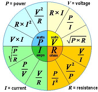
A more complex formula wheel, by "VampireBaru".
Example series and parallel circuits
 |
Left: A simple parallel circuit, where IT = I1 + I2. If the battery is 12 volts, then the voltage across each resistor is 12 volts. This likewise applies if the resistors were instead a radio and a lamp. If the battery is large, and well charged, then how much current the radio draws has very little impact on the voltage on the lamp, and therefore its brightness.
Centre Left: A simple series circuit, where the current through both devices is the same, and depends on the total resistance, say 2 + 10 = 12 ohms, meaning 1 amp would flow were it a 12 volt battery. The voltage is divided depending on the values of each resistor, with these values, it is 2 and 10 volts, totalling the 12 of the battery.
Centre Right: A more complex series-parallel circuit, but not a recommended one, as we cannot be sure of how well the current will be shared. Were the battery 12 volts, and the resistor 250 ohms, then about 40 mA would be available to the LEDs. If the forward voltage curves are identical, then it would be shared perfectly, 20 mA each. If one is red, at about 2 volts VF and the other is blue, with a 3 volt VF, the red one will pull the voltage to 2 volts, below the point the blue will draw any, and so all of the 40mA will flow in the red one, probably shortening its life. If the LEDs are similar, then one might take the voltage down to 1.9 volts, at which point the other will still conduct some current, maybe only 10 mA while the first uses 30. This demonstrates the interaction of two parallel devices in a circuit where current is restricted by a resistor.
Right: Another kind of energy source is the current source, which attempts to maintain a constant current in its load. One can be made using an LM317 variable voltage regulator IC and a resistor, the current in this resistor setting the current in the circuit. The '317 is really a 1.25 volt regulator, and this maintains 1.25 v between the output and adjust terminal, so 12.5 ohms means 100 mA flows. This circuit could be used to power one or more higher powered LEDs in series, maintaining the current reasonably independent of the VF, and of the voltage drop in the wires to it or them. This circuit demonstrates that available current is shared depending on the relative values of the two parallel components. The two resistors in parallel is 1/(1/90 + 1/180) = 60 ohms, and so the voltage across them is 6 volts. |
kHz and MHz
New questions in this section ask you to apply the metric M for Mega, and k for kilo; and Hz for Hertz, the unit for frequency to correctly form kHz and MHz.
Mega indicates 1 million (1,000,000) of the base unit, and kilo one thousand (1000).
kHz, with lower case "k" is used in audio and lower radio frequencies. Examples are 1kHz, a fairly irritating tone. Towards the upper-end of the human hearing range, that annoying whistle you heard from an old-style (tube) TV is 15.750 kHz (US B&W) or 15.734 kHz TV (NTSC); or 15.625 kHz (PAL or SECAM in Oz, UK, EU, and the Soviet block). ABC Radio National in Sydney is on 576 kHz.
MHz is used in used in 27 MHz (CB), 100.1 MHz (FM radio), 144 MHz (2 metres), or 477 MHz (UHF CB). In is important to note the use of the capital or upper-case "M"; and likewise the upper, then lower-cases in Hz. A small "m" has a significantly different meaning, 1 milliHertz is one cycle per 16⅔ minutes (!), or 3.6 times per hour.
I have written some notes on Division.
Relevant Questions
These are the actual exam questions relating to this knowledge.
T5C08
What is the formula used to calculate electrical power in a DC circuit?
A. P = E × I
B. P = E / I
C. P = E - I
D. P = E + I
Remember back to the first example, the biggest figure of 240 V, 10 A and 2400 W is the the power 2400 W, so it must be multiplication, answer A.
T5C09
How much power is delivered by a voltage of 13.8 volts DC and a current of 10 amperes?
A. 138 watts
B. 0.7 watts
C. 23.8 watts
D. 3.8 watts
Remember you can discard the addition and subtraction. Multiply 13.8 by 10 and get the 138 watts, as per P = I × E. Answer A.
T5C10
How much power is delivered by a voltage of 12 volts DC and a current of 2.5 amperes?
A. 4.8 watts
B. 30 watts
C. 14.5 watts
D. 0.208 watts
Chuck out the addition; and remember we are after power (P), having been given E and I, so we multiply, getting 2 times 12 (=24), plus a half of 12 (=6), giving 30. P = E × I = 12 × 2.5 = 30. Answer B.
T5C11
How much current is required to deliver 120 watts at a voltage of 12 volts DC?
A. 0.1 amperes
B. 10 amperes
C. 12 amperes
D. 132 amperes
We are after current (I), given Power (P) and voltage (E), so time to divide, but which way? Given P = E × I, we need to get rid of the E from the I side, meaning we divide P by E on the other. I = P / E, = 120 / 12 = 10 amperes, answer B.
T5C12
What is impedance?
A. The opposition to AC current flow
B. The inverse of resistance
C. The Q or Quality Factor of a component
D. The power handling capability of a component
As resistance is the opposition to DC current, impedance is the opposition to the flow of AC current, so answer A.
T5C13
What is the abbreviation for kilohertz?
A. KHZ
B. khz
C. khz
D. kHz
k for kilo, Hz for Hertz; so kHz, answer D.
T5C07
What is the abbreviation for megahertz?
A. MH
B. mh
C. Mhz
D. MHz
M for Mega, Hz for Hertz, so MHz, answer D.
T5D01
What formula is used to calculate current in a circuit?
A. I = E × R
B. I = E / R
C. I = E + R
D. I = E - R
Chuck out the addition and subtraction. E = I × R, so flip that around to I = E / R. Answer B.
T5D02
What formula is used to calculate voltage in a circuit?
A. E= I × R
B. E= I / R
C. E= I + R
D. E = I - R
Again, give the + and - options the heave-ho. Get your Gaelic on, and remember EIRé, so it is E = I × R, answer A.
T5D03
What formula is used to calculate resistance in a circuit?
A. R = E × I
B. R = E / I
C. R = E + I
D. R = E - I
A high-school transposition question: We know E = I × R, and we need to move the I to the other side to get R. As it is a multiplication relationship, we need to divide it by I, to cancel it out. What you do on one side you must do on the other, so on that side we get E / I. Tidy the order up, and you get R = E / I, answer B.
T5D04
What is the resistance of a circuit in which a current of 3 amperes flows when connected to 90 volts?
A. 3 ohms
B. 30 ohms
C. 93 ohms
D. 270 ohms
You need to find R from I and E, so flip E = I × R to R = E / I = 90 / 3 = 30 ohms, answer B.
T5D05
What is the resistance in a circuit for which the applied voltage is 12 volts and the current flow is 1.5 amperes?
A. 18 ohms
B. 0.125 ohms
C. 8 ohms
D. 13.5 ohms
Like the previous question, R = E / I = 12 / 1.5 = 8. So, C. As a check, the current is over 1 amp, so the resistance must be less than 12 ohms, but if it was a fraction of an ohm, then the current would be well over 12 amps.
T5D06
What is the resistance of a circuit that draws 4 amperes from a 12-volt source?
A. 3 ohms
B. 16 ohms
C. 48 ohms
D. 8 ohms
Another "Find R from E and I", so R = E / I = 12 / 4 = 3 ohms, answer A.
T5D07
What is the current flow in a circuit with an applied voltage of 120 volts and a resistance of 80 ohms?
A. 9600 amperes
B. 200 amperes
C. 0.667 amperes
D. 1.5 amperes
This isn't a "Do destructive things with stupidly large currents" You-Tube channel, so not the first one. Even 200 amps is unusual in Ham radio (and it is an addition answer, so probably wrong).
R = I × E so I = E / R = 120 / 80 = 12 / 8 = 3 / 2 = 1.5 amps, answer D.
By the way, 120 volts is the nominal mains voltage for lower powered equipment in North America.
T5D08
What is the current flowing through a 100-ohm resistor connected across 200 volts?
A. 20,000 amperes
B. 0.5 amperes
C. 2 amperes
D. 100 amperes
Another I = E / R, just with the position of the values swapped. So, I = 200 / 100 = 2 / 1 = 2 amps. Too easy! Answer C.
T5D09
What is the current flowing through a 24-ohm resistor connected across 240 volts?
A. 24,000 amperes
B. 0.1 amperes
C. 10 amperes
D. 216 amperes
Another "Find I from E and R", so I = E / I = 240 / 20 equals 10 amps, answer C. For Aussies, this is roughly the current used by a 2400 watt heater.
Why 240 volts in America? Most US homes are supplied with "split-phase" power, where the pole transformers are what electronics folk call "centre tapped", with this centre tap connected to ground / earth, forming the neutral; giving 120 volts from one hot to neutral for iThingy chargers, lamps, and smaller radios, but 240 volts between the the hots for things like clothes dryers, and for Amateurs, 1500 watt output linear amplifiers, which require power not only for the RF output, but for the filament supply of the big valves / tubes, and for fans, etc.
T5D10
What is the voltage across a 2-ohm resistor if a current of 0.5 amperes flows through it?
A. 1 volt
B. 0.25 volts
C. 2.5 volts
D. 1.5 volts
E = I × R = 0.5 × 2 = 1, so A.
T5D11
What is the voltage across a 10-ohm resistor if a current of 1 ampere flows through it?
A. 1 volt
B. 10 volts
C. 11 volts
D. 9 volts
E = I × R = 1 × 10 = 10, so B.
T5D12
What is the voltage across a 10-ohm resistor if a current of 2 amperes flows through it?
A. 8 volts
B. 0.2 volts
C. 12 volts
D. 20 volts
E = I × R = 2 × 10 = 20, so D.
T5D13
In which type of circuit is DC current the same through all components?
A. Series
B. Parallel
C. Resonant
D. Branch
This is the series curcuit, answer A.
A dude called Kirchhoff once said that the sum of current entering a node or junction is the same as the current leaving it, so when the junction has two connections these current are the same.
T5D14
In which type of circuit is voltage the same across all components?
A. Series
B. Parallel
C. Resonant
D. Branch
Kirchhoff also said that the voltage across all components in a parallel circuit is the same, answer B.
Connect a Ham transceiver and a CB across a 12 volt battery and both have 12 volts across them. Ditto a lamp and a small fan on the same circuit of your home power; both have the same 120 volts, or same 230 volts, applied to them.
That wasn't too hard, was it?
Comment on High Currents
You will note high currents in the distractors above.
Where would the 100 or 200 amps be seen?
This is the starting current for a small petrol / gasoline car engine. Diesels are often higher, thanks to the higher compression, they are after all Compression Ignition engines, and car run on things like SVO - straight vegetable oil, or biodiesel.
In ham radio, in a large inverter based supply which generates higher voltages to run a 1500 watt amplifier needs a very high input current. Since this would require extra batteries, and probably a second alternator, smarter folk would make the set-up at least 24 volts, to make the current a little more sensible. Or they'd use the traction battery powered DC to AC converter built into a Chinese EV to power the "Linear", as these amplifiers are called, be they actually linear, or not.
Home use stick welders typically provide a current of over 100 amps, industrial ones up to 1000 A. Shipbuilding may use welders output up to 40,000 amps.
Very large transmitters, such as HCJB's HC100, a 100kW unit used for global shortwave broadcasting might draw 220 amps per phase at 480 volts (delta). These include a transformer to step the voltage down to power the filament in the main valve, which draws 300 amps at 10 volts AC. Given R = 10 / 300 = 0.0333 Ω or 33.3 μΩ, this is a very chunky filament. And it would be even lower when cold.
As for the very large currents, these might be seen in things like aluminium smelters, where massive currents keep the alumina molten, and causes the electrolysis to metallic aluminium (aluminum). The massive energy use to make aluminium makes recycling cans and other products most worthwhile.
The other place very large current are seen is during heavy short circuits in large electrical installations. These can cause significant damage. In addition to the arcs, sparks, fire and explosions, the huge magnetic forces can buckle busbars.
Very large current pulses are also used in various forms of scientific research.
Note for Brits & Northern Irish re the Ring Main
The concept of a circuit where a cable leaves the fusebox or breaker board, and returns to it after passing through a loop may have the implication of a series circuit, but this is NOT the case. The cable contains three conductors; the line (aka phase, aka active), the neutral, and the earth. At each outlet, the 3 wires are connected, and looped to the bext and this is a PARALLEL connection. The only difference between this and any other system is that once the cable reaches the furthest room along, say, the east wall, it loops back, and supplies outlets along the western side of the building, before returning to the board. Each outlet has 240 volts (officially 230 volts) on it. The benefit of the looping ring is that current can be shared over the two clockwise and anti-clockwise lines.
On to: Component Symbols & Schematic Diagrams
You can find links to lots more on the Learning Material page.
Written by Julian Sortland, VK2YJS & AG6LE, March 2025.
Tip Jar: a Jefferson (US$2), A$3 or other amount / currency. Thanks!